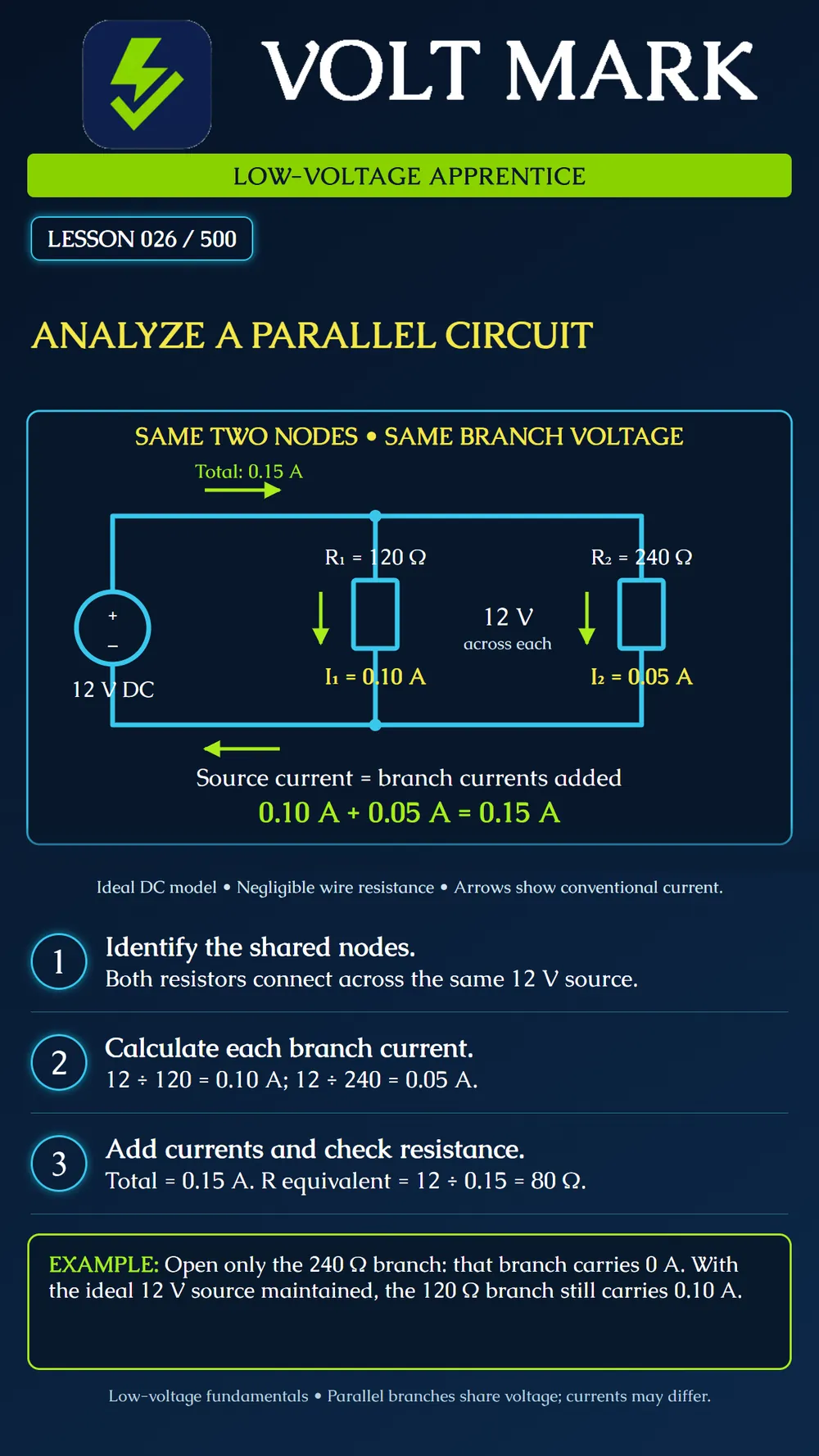
Recognize two parallel resistor branches, calculate each branch current and check the total source current and equivalent resistance.
Parallel branches connect between the same two circuit nodes. They therefore have the same voltage across them. Each branch current depends on that branch's resistance. At the junction, source current equals the sum of branch currents. For ideal resistors, 1/R equivalent = 1/R1 + 1/R2. Two positive resistances in parallel have an equivalent resistance smaller than either individual resistance.
Source: 12 V DC. R1: 120 Ω. R2: 240 Ω. Branch 1: I1 = 12 V ÷ 120 Ω = 0.10 A = 100 mA. Branch 2: I2 = 12 V ÷ 240 Ω = 0.05 A = 50 mA. Source current: I total = 0.10 + 0.05 = 0.15 A = 150 mA. The larger resistance takes less current at the same voltage.
From the source's perspective: R equivalent = 12 V ÷ 0.15 A = 80 Ω. An independent two-resistor check gives: R equivalent = (120 × 240) ÷ (120 + 240) = 80 Ω. The answer is smaller than 120 Ω and 240 Ω, as expected for these two positive parallel resistances. Do not add the two resistances as if they were series.
Erase a short segment of conductor in only the 240 Ω branch on a copy of the drawing. Do not erase a shared source or return conductor. That branch is now open and carries no steady current. With the ideal source still maintaining 12 V, the intact 120 Ω branch continues to carry 0.10 A. Total source current becomes 0.10 A. Now instead erase the common source connection before the split. Both branches lose their complete connection to that source. The two erased locations produce different results. Name the location precisely rather than saying only “a wire is open.”
A second worksheet has an ideal 24 V source across two parallel resistors, 240 Ω and 480 Ω. I1 = 24 ÷ 240 = 0.10 A. I2 = 24 ÷ 480 = 0.05 A. I total = 0.15 A. R equivalent = 24 ÷ 0.15 = 160 Ω. Voltage across each branch remains 24 V in this model.
Real low-voltage power distribution may have shared wiring voltage drop, output current limits, protective devices and electronic loads. One fault can affect other branches through those shared elements. The worksheet's independent-branch result assumes its ideal source and intact common connections. Do not interpret this diagram as approval to parallel arbitrary supply outputs, batteries or system circuits. It illustrates loads across one source. A real device's required polarity and voltage still matter. Components merely drawn beside one another are not necessarily parallel; trace their actual connections.
Q: What do these branches share? A: The same two nodes and therefore the same voltage. Q: Must branch currents be equal? A: No. Q: What is total source current in the main example? A: 0.15 A. Q: Why is 360 Ω incorrect as the equivalent resistance? A: That is the series sum, not the parallel equivalent. Q: Does opening one branch always leave every real system branch unaffected? A: No; the result depends on shared connections, source behavior and protection.
Parallel branches share voltage. Calculate each branch current, then add them. Twelve volts across 120 ohms gives 100 milliamps; across 240 ohms it gives 50 milliamps. The source provides 150 milliamps, and the equivalent resistance is 80 ohms.
Mistake: dividing the 12 V equally between these parallel branches. Correction: each spans the same two nodes, so each has 12 V in the stated ideal model. Mistake: adding 120 ohms and 240 ohms to obtain 360 ohms. Correction: add branch conductances or divide voltage by total current; the equivalent is 80 ohms, smaller than either positive branch resistance. Mistake: assuming both branch currents are equal. Correction: calculate each using its resistance; the 240-ohm branch takes 50 mA, half the 120-ohm branch's 100 mA. Mistake: assuming an open anywhere affects only one branch. Correction: distinguish an individual branch opening from a shared-source or shared-return opening; the latter affects both paths in this drawing.
OpenStax, Physics, 19.3 Parallel Circuits: https://openstax.org/books/physics/pages/19-3-parallel-circuits The worksheet values and fault-location exercises are original teaching examples.
Texas journeyman, 15 questions, scored by topic against the 70% mark. No card, and no account needed to start.
Free study material for low-voltage apprentices. This is a national foundation course: requirements differ by state and by local jurisdiction, and a practice that is common in one place is not a rule everywhere. Nothing here is a licence, a certification, or authority to work unsupervised, and completing it does not count as apprenticeship hours or continuing-education credit. Check the codes adopted where you are working, the licensing authority for that work, and your employer's safety programme. VoltMark is not affiliated with, endorsed by, or sponsored by NFPA, OSHA, NICET, BICSI, FOA, or any state or local licensing authority.

Electrician licensing exam prep: practice questions, timed exam simulations, and step-by-step help finding every answer in the NEC.