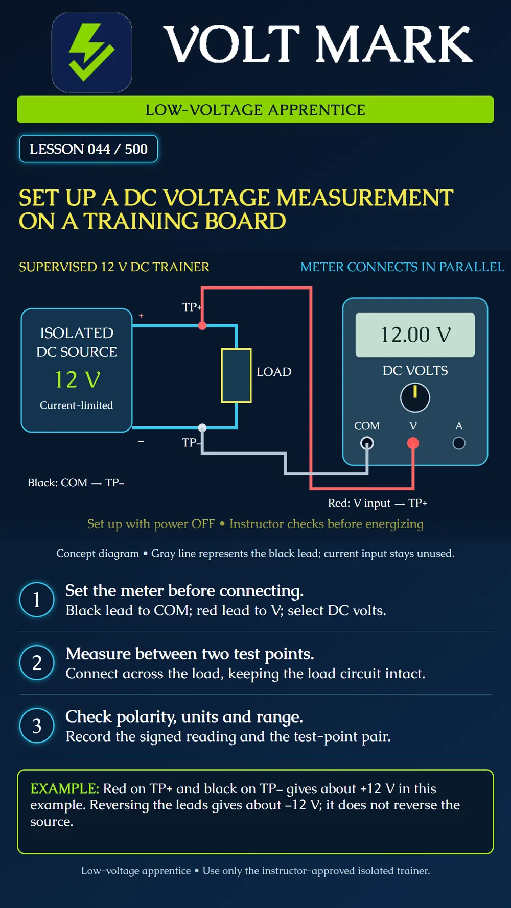
Prepare a DC voltage measurement on an instructor-approved isolated, current-limited low-voltage training board. Identify the inputs, function, test points, expected polarity, and recorded units.
Use the specified board and its instructions. The instructor confirms the source, limits, protection, connections, and supervision. This activity is not permission to probe building equipment, mains terminals, battery banks, or unknown circuits. A bench supply's adjustable display alone does not establish that the entire setup is appropriate.
Read the board diagram and locate TP+ and TP−. Identify the load between them. Inspect the selected meter and leads as taught in Lesson 043. Confirm their suitability for the task. With the trainer off, put the black lead in COM and the red lead in the voltage input. Select DC voltage and an appropriate range under the meter instructions. Some meters require a secondary function selection; verify the displayed mode.
Voltage describes the difference between two points. The voltage meter is connected in parallel across the points being compared. In this example the load remains connected to the source, and the meter reads across the load. Do not open the load circuit to insert a voltage meter in series. Do not use a current input for this voltage measurement.
For this exercise, the instructor checks the powered-off setup and the approved connections before energizing the board. Use the permitted shrouded connections or probes and keep fingers behind guards. Prevent adjacent test points from being bridged. Follow the board procedure for turning on and taking the reading; do not improvise changes with power applied.
For the idealized 12 V example, red on TP+ and black on TP− produces a positive reading near 12 V. A negative reading means the red point is at lower potential than the black point under the selected reference. It does not automatically prove a faulty supply. Check point identification and lead placement.
Record the actual signed value, unit, test-point pair, source setting, and load state. An example display of 12.00 V is not a guaranteed reading or acceptance tolerance for every trainer. The instructor supplies the allowed range. Do not silently round an unexpected measurement until it appears acceptable.
Turn off the trainer through the approved procedure before rearranging this exercise. Disconnect and store the equipment as instructed. Explain unexpected readings rather than repeatedly changing settings without a plan. This lesson teaches a measurement setup, not a procedure for proving field equipment safe to touch.
The instructor gives the learner two labeled points and asks for their voltage difference. Before power is applied, the learner traces both meter leads to the jacks, names the selected function, identifies which point is the reference, and predicts the sign. After the approved measurement, the learner records the reading and compares it with the prediction.
On paper, reverse the red and black test-point assignments. Predict the new signed reading for an ideal 12 V source. The magnitude remains 12 V and the sign changes. Any physical reversal is done only with the trainer off and under the instructor's procedure.
A paper trainer sheet states that TP+ is 12 V higher than TP−. The planned DC-voltage setup has black in COM and red in the voltage input, with red assigned to TP+ and black to TP−. First identify the quantity: voltage difference, so the meter is across the two points rather than inserted into the load path. Next name the reference: TP− is the point connected to black. The predicted ideal result is +12 V. On a second paper drawing, red is assigned to TP− and black to TP+. The predicted ideal result becomes −12 V because the comparison direction reverses. The negative sign does not by itself show a damaged source. These are paper predictions, not measured results or permission to rearrange a powered trainer.
Mistake: placing the voltage meter in series with the load. Correction: identify the two points whose difference is required and use the specified parallel arrangement. Mistake: calling every negative display a failed supply. Correction: record the sign and named red/black test points before interpreting polarity. Mistake: copying 12.00 V from the illustration as the actual test result. Correction: record the observed value and conditions; the example is not an instrument reading from your board.
Fluke, How to measure DC voltage with a digital multimeter: https://www.fluke.com/en-ie/learn/blog/digital-multimeters/how-to-measure-dc-voltage-with-a-digital-multimeter Source checked September 30, 2026. Follow the actual meter and trainer instructions.
Texas journeyman, 15 questions, scored by topic against the 70% mark. No card, and no account needed to start.
Free study material for low-voltage apprentices. This is a national foundation course: requirements differ by state and by local jurisdiction, and a practice that is common in one place is not a rule everywhere. Nothing here is a licence, a certification, or authority to work unsupervised, and completing it does not count as apprenticeship hours or continuing-education credit. Check the codes adopted where you are working, the licensing authority for that work, and your employer's safety programme. VoltMark is not affiliated with, endorsed by, or sponsored by NFPA, OSHA, NICET, BICSI, FOA, or any state or local licensing authority.

Electrician licensing exam prep: practice questions, timed exam simulations, and step-by-step help finding every answer in the NEC.