Create a device-by-device power inventory, including indirect loads, before evaluating supply capacity.
Start with the approved drawings and exact installed product documentation. Assign an identifier to each supply and each powered device. Identify which supply provides operating power; a communication or trigger wire does not necessarily provide it.
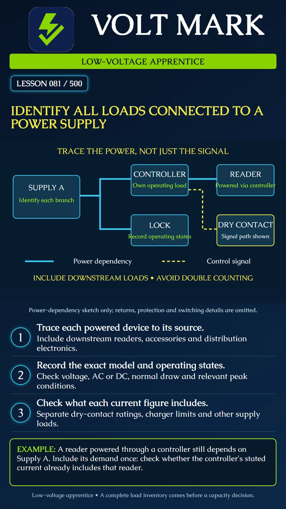
The fictional sketch shows Supply A feeding a controller and a lock branch. The controller supplies a reader. That reader ultimately depends on Supply A even though it is not directly connected to the supply's terminals. The sketch omits switching, return conductors and protection. It is a teaching map, not a wiring diagram.
Look for expansion boards, powered distribution modules, readers, keypads, powered sensors, sounders and other accessories in the actual system. This is a search checklist, not a requirement to install these devices. Follow each documented branch until all powered equipment has a source assignment.
Use exact model and option information. A similar-looking model can require a different voltage or draw different current. Record AC or DC, permitted input range and the documentation revision. Do not infer Class 2 status from a 12 V or 24 V label.
A passive dry contact switches or reports a condition; its contact current rating is not the device's operating current. Any associated relay coil or powered electronics may have a separate demand. A supervised input can also have sensing current, which must be handled according to the equipment documentation rather than guessed from the contact rating.
Altronix's AL600ULACM documentation illustrates why this distinction matters: the equipment has trigger inputs, powered outputs, dry-contact options and alternative power-source arrangements. Those features belong to that product and configuration; the poster is not its connection diagram.
Check whether a controller current figure describes only its electronics or already includes powered peripherals. If the document gives an inclusive total, do not add the same reader again. If it excludes the reader, account for the reader separately at the appropriate supply boundary. With an intervening converter, use documented input demand or an appropriate efficiency-based calculation; currents on different voltage rails cannot simply be added.
Record relevant idle, active, alarm, startup and simultaneous-operation conditions from the actual documents. Do not assume the current observed during one quiet moment is the maximum. A relay or lock may draw power in a different state than expected. Later lessons use this information to build the normal and peak load schedule.
A standby battery can supply energy during an outage and receive charging current when normal power returns. Record the applicable charger and load-output constraints. Do not automatically add a published charger maximum to a load-output sum or subtract it from rated output without reading how the manufacturer defines those ratings. Altronix's installation guide lists separate model-dependent output and charging specifications; it is not a universal sizing formula.
Use approved records and supervised verification. Unresolved source assignments stay marked unknown. Do not disconnect operating life-safety or access-control equipment to discover where it gets power.
Supply A feeds controller C1 and lock L1. Reader R1 is supplied through C1. A passive contact S1 reports status to C1. A separate network switch supplies camera V1 by PoE.
Identify C1, L1 and R1 as dependent on Supply A. Record S1 as an interface and determine what input demand is already included in C1's documentation. V1 belongs to the switch's power inventory. Do not move V1 into Supply A's total merely because both systems communicate on the network.
Supply ID and exact model: Device ID, model, quantity and options: Power path, including intermediate devices: Operating voltage and AC/DC: Current or power figures and operating states: What the stated figure includes/excludes: Document and revision: Unresolved source or rating question: Verifier and date:
In a fictional update, Supply A powers C1 and L1, and C1 powers reader R1. Supply B powers an added sounder S2. A dry contact from C1 triggers S2; that contact does not supply sounder power. The stated C1 demand already includes R1. Draw the two power inventories, identify which demand must not be added twice, and name the missing information before capacity can be checked.
Supply A's inventory includes C1 with its included reader demand and L1. Keep R1 visible as an indirect load but do not add its current a second time to that inclusive C1 figure. Supply B includes S2; record C1's dry contact as its trigger interface, not its energy source. Exact model demands, operating conditions, supply and branch limits, and applicable charging or startup information still require verification before capacity can be approved.
Mistake: Leaving reader R1 out because it connects through C1 rather than directly to Supply A. Correction: Trace the power path back to the supply boundary and account for R1 once, checking whether C1's stated demand already includes it.
Mistake: Adding a relay contact rating to the supply-current inventory. Correction: Distinguish contact switching capacity from the documented demand of the coil, electronics, or sensing input.
Mistake: Adding camera V1 to Supply A because it shares network communication with the controller. Correction: Assign V1 to the switch that supplies its PoE power and keep communication links distinct from power paths.
Altronix - AL600ULACM product specifications: trigger inputs, powered and dry-contact outputs, one- or two-source arrangements. https://www.altronix.com/products/AL600ULACM Altronix - ACM Series Installation Guide: model-dependent supply/output and charger specifications. Use the exact revision applicable to installed equipment. https://altronix.com/library/pdf/installation_instructions/ACMseries_Temp_PowerDIP.pdf
Diagram and named exercise devices are fictional. No capacity approval or connection instructions are provided.
Texas journeyman, 15 questions, scored by topic against the 70% mark. No card, and no account needed to start.
Free study material for low-voltage apprentices. This is a national foundation course: requirements differ by state and by local jurisdiction, and a practice that is common in one place is not a rule everywhere. Nothing here is a licence, a certification, or authority to work unsupervised, and completing it does not count as apprenticeship hours or continuing-education credit. Check the codes adopted where you are working, the licensing authority for that work, and your employer's safety programme. VoltMark is not affiliated with, endorsed by, or sponsored by NFPA, OSHA, NICET, BICSI, FOA, or any state or local licensing authority.

Electrician licensing exam prep: practice questions, timed exam simulations, and step-by-step help finding every answer in the NEC.