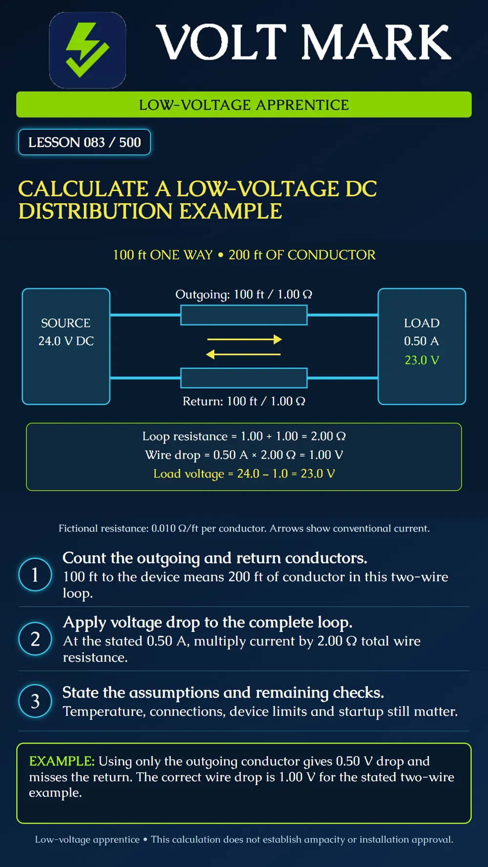
Calculate conductor resistance and voltage drop in a simple two-wire DC circuit while keeping assumptions visible.
Source voltage at its output terminals under the stated load: 24.0 V DC. Load current at the evaluated operating point: 0.50 A. One-way cable route: 100 ft. Two equal conductors, each 100 ft long. Assumed resistance per conductor: 0.010 ohm per foot at the evaluated condition. Additional connection, protection-device and switching losses: omitted for this simplified exercise.
The resistance is a fictional teaching value, not a wire-gauge specification. No actual cable product is selected. The load is assumed to draw the stated current at this operating point; a constant-power or resistive load can behave differently as voltage changes.
R = length x resistance per unit length. Outgoing: 100 ft x 0.010 ohm/ft = 1.00 ohm. Return: 100 ft x 0.010 ohm/ft = 1.00 ohm.
R loop = 1.00 + 1.00 = 2.00 ohms. There are 200 ft of conductor, although the source and device are 100 ft apart along the route. Speco's paired-wire guidance expressly includes both feed and return. If a table already gives loop resistance or paired-run voltage drop, do not double it again.
V drop = I x R loop. 0.50 A x 2.00 ohms = 1.00 V. Each equal conductor contributes 0.50 V of that drop. The same 0.50 A circulates through both; the source current is not 1.00 A merely because two conductors are present.
V load = V source - V drop. 24.0 - 1.0 = 23.0 V. This is the voltage between the device's two supply terminals in the simplified model. The return conductor is part of the circuit, not an ideal zero-resistance reference.
As an optional arithmetic check, wire loss is I squared x R loop = 0.50 squared x 2.00 = 0.50 W. Source power is 24.0 x 0.50 = 12.0 W; load power is 23.0 x 0.50 = 11.5 W. The difference is the modeled conductor loss.
Belden's 9578 product information illustrates that conductor DC resistance is a specified cable property. Check the actual product, units, temperature basis and whether the value is nominal or maximum. Do not use a nominal room-temperature value as a guaranteed worst-case design limit without further evaluation. A conductor's resistance and its allowable current are different properties.
Include relevant connection and device drops. Evaluate the minimum source voltage, including applicable battery operation, and the actual load behavior. Repeat for relevant peak or startup conditions. Compare the resulting device-terminal voltage with that device's permitted range. Do not compensate by raising a supply voltage without checking every connected device and the approved design.
This model describes one load and one dedicated outgoing/return pair. Shared feeders or shared returns require segment-by-segment currents. A simple doubling shortcut is not automatically valid for every topology.
Source voltage and operating condition: One-way length and topology: Conductor resistance source, units and temperature: Loop/segment resistance: Evaluated current: Connection and equipment drops: Calculated device voltage: Device limits and unresolved assumptions:
Mistake: Using only the 100-foot outgoing conductor in the resistance calculation. Correction: Include the equal 100-foot return: the exercise has 200 conductor-feet and 2.00 ohms total loop resistance.
Mistake: Doubling 2.00 ohms again after it is already identified as loop resistance. Correction: Check whether the input is per-conductor or complete-loop data before applying any length multiplier.
Mistake: Adding outgoing and return current to claim the source supplies 1.00 A. Correction: Use the same 0.50 A series current through both conductors; add their voltage drops, not their currents.
Mistake: Treating the fictional 0.010 ohm/ft as a real cable-selection rating. Correction: Obtain the actual product resistance, units, temperature basis, and relevant design limits for the installed cable.
Speco Technologies - How to calculate DC voltage drop for long wire runs: paired feed-and-return length and load-current relationship. https://info.specotech.com/how-to-calculate-dc-voltage-drop-for-long-wire-runs Belden - 9578 product specifications: conductor DC resistance as product data. The example does not use or specify this product. https://www.belden.com/products/cable/electronic-wire-cable/multi-conductor-cable/9578
Calculated values do not establish conductor ampacity, circuit classification, equipment suitability or code compliance.
Texas journeyman, 15 questions, scored by topic against the 70% mark. No card, and no account needed to start.
Free study material for low-voltage apprentices. This is a national foundation course: requirements differ by state and by local jurisdiction, and a practice that is common in one place is not a rule everywhere. Nothing here is a licence, a certification, or authority to work unsupervised, and completing it does not count as apprenticeship hours or continuing-education credit. Check the codes adopted where you are working, the licensing authority for that work, and your employer's safety programme. VoltMark is not affiliated with, endorsed by, or sponsored by NFPA, OSHA, NICET, BICSI, FOA, or any state or local licensing authority.

Electrician licensing exam prep: practice questions, timed exam simulations, and step-by-step help finding every answer in the NEC.