Create a traceable intrusion equipment schedule that a supervisor can reconcile with the plans, zone list and installation records.
An equipment schedule tells the project team what each listed item is and where it belongs. A useful row leads from a drawing tag to a specific device, its location and its system assignment. A purchasing total alone cannot do that.
Begin with the approved project scope and current drawing revision. Use a stable, unique identifier for each separately tracked field device. Write the location clearly enough for another authorized technician to find it. Describe the device function and record the manufacturer and exact model once selected and approved. Mark unresolved choices as pending. Do not fill blanks with guesses.
Manufacturer worksheets illustrate why equipment and programming records must stay connected. The cited DSC installation guide contains zone records, module records and wireless device records. They distinguish location and zone information from module slot and serial information. Use the applicable product documentation to determine which identifiers your system needs; this lesson's sample is an original exercise, not a copy of that manufacturer's worksheet.
The schedule is not a promise that equipment has been installed or tested. Keep those states distinct. A design assignment may be planned before a panel has been installed. An installed device may still need configuration and testing. Write the date, person and evidence reference supporting each status change. Use the project's controlled records for sensitive information; passwords and access credentials do not belong in an ordinary equipment list.
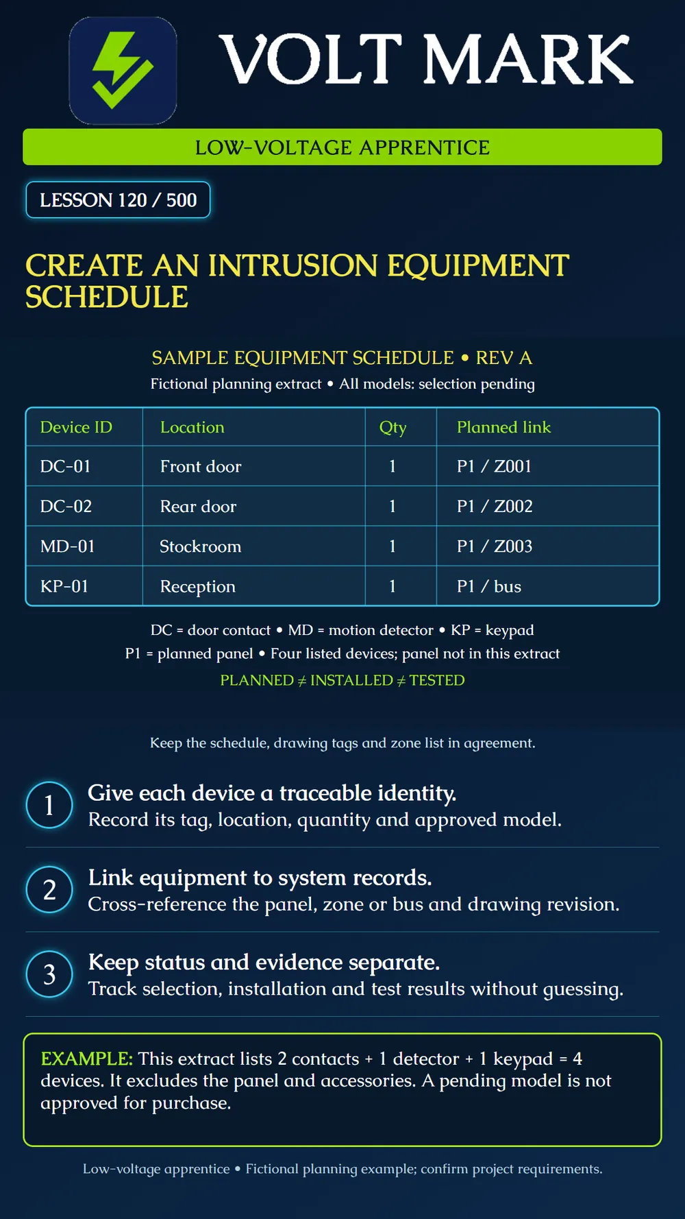
The poster is a four-row extract, not a complete bill of materials: DC-01 | door contact | front door | quantity 1 | planned P1 / Z001 DC-02 | door contact | rear door | quantity 1 | planned P1 / Z002 MD-01 | motion detector | stockroom | quantity 1 | planned P1 / Z003 KP-01 | keypad | reception | quantity 1 | planned P1 / bus
For all four rows, model selection is pending, installation is not verified and testing is not verified. P1 is a fictional panel reference, not a product compatibility claim. The keypad's bus reference is not a zone assignment or an approved bus address. Enter the actual address, slot or other identity only when the selected equipment and approved design establish it.
Two contact devices plus one detector plus one keypad equals four devices in this extract. The panel is excluded from that subtotal. A complete project schedule may need separate rows for its controller, enclosure, power supply, battery, communicator, expanders and accessories. Determine actual scope from the project; this example does not establish required quantities.
Record a proposed substitute as a proposal. Have the responsible designer or qualified installer resolve compatibility and system impacts before treating the substitution as approved. Update related records together, including drawing references and power calculations where affected. Retain revision history so an earlier order or field label can be traced.
Using a training drawing provided by your supervisor, enter these four devices. Circle each matching drawing tag. Identify the missing model selections and list who must resolve them. Add separate columns for planned, installed and tested status. Compare the row count with the scope and label exclusions. Have your supervisor introduce one changed location; revise the schedule and drawing reference together rather than silently replacing the original record.
Revision/date; device ID; function; location; quantity; manufacturer/model; selection approval; panel reference; zone or bus identity; drawing/detail reference; installation status/date; serial number where applicable; test record reference; unresolved issue and owner. Tailor fields to the system and approved project process. No universal county form is implied.
Mistake: Assigning KP-01 to Z004 because it is the fourth row. Correction: Keep its planned bus relationship separate from zone numbering and enter an address or slot only when the selected design establishes it.
Mistake: Counting P1 as a fifth device in the four-row extract. Correction: Total only the listed quantities and state that the referenced panel is outside this extract; add its own row when the project scope requires it.
Mistake: Marking the listed devices installed and tested because their tags match the plan. Correction: Keep planned, installed, and tested status separate and attach actual evidence to each status change.
Mistake: Silently replacing a pending model with an available substitute. Correction: Record the proposal, obtain the required compatibility and selection disposition, and update linked drawings and calculations with revision history.
Primary manufacturer source checked September 30, 2026: DSC / Johnson Controls, PowerSeries Pro v1.1 Installation Guide, records section (zone, module and wireless device records): https://docs.johnsoncontrols.com/visonic/api/khub/documents/XbKOGwoTaNGqYZ2ze7Gu8g/content Source used for the distinction between manufacturer record categories. The fictional IDs, schedule, arithmetic and practice activity are original instructional examples. Consult documentation for the actual installed model and applicable project requirements.
Texas journeyman, 15 questions, scored by topic against the 70% mark. No card, and no account needed to start.
Free study material for low-voltage apprentices. This is a national foundation course: requirements differ by state and by local jurisdiction, and a practice that is common in one place is not a rule everywhere. Nothing here is a licence, a certification, or authority to work unsupervised, and completing it does not count as apprenticeship hours or continuing-education credit. Check the codes adopted where you are working, the licensing authority for that work, and your employer's safety programme. VoltMark is not affiliated with, endorsed by, or sponsored by NFPA, OSHA, NICET, BICSI, FOA, or any state or local licensing authority.

Electrician licensing exam prep: practice questions, timed exam simulations, and step-by-step help finding every answer in the NEC.