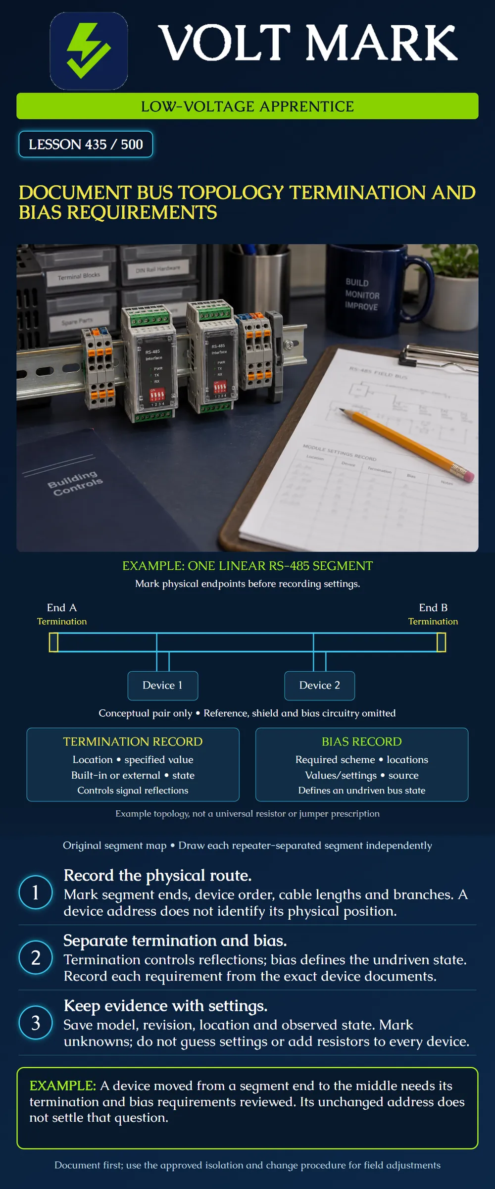
Produce a reviewable RS-485 bus record that distinguishes physical topology, termination and bias rather than treating them as one setting.
The poster shows one conceptual linear differential pair with two illustrated device taps. Termination symbols bridge the pair at its two physical ends. Power, signal reference, shield and actual bias circuitry are omitted to make the documentation concepts clear. Their omission is not permission to omit them in an installation. The picture specifies no resistor value, cable rating, permitted tap length or device count.
Identify the actual communication segment and label both ends. Trace the cable route, device connection order, junctions and any repeaters. Record cable identification and documented lengths. A device's logical address does not reveal where it sits on the physical cable.
The two devices in the illustration connect across the pair; they are not series electrical loads. Their short vertical lines are conceptual taps, not approved stub dimensions. The line crossing the first tap's other conductor is not marked as a junction; it does not short the pair. Actual drawings should use clear terminal and conductor identification.
An Ethernet switch diagram is not a substitute for a serial-bus drawing. If a field route has multiple branches or an apparent star, document it accurately and compare it with the approved design. Do not redraw it as a straight trunk merely because that is what was expected.
Termination manages signal reflections associated with transmission-line impedance discontinuities. The appropriate arrangement depends on the interface and application. A linear bidirectional RS-485 example commonly uses termination at its two physical ends, as illustrated.
Texas Instruments' RS-485 Design Guide discusses a linear bus, short stubs, termination and receiver behavior. Those concepts explain why cable geometry and component loading matter. They do not establish one installation limit for all building controls products.
For each termination location, record the equipment tag, exact terminal or switch reference, required value or built-in arrangement, required state, observed state and supporting manual section. Determine whether a built-in terminator is already present before treating an external component as missing.
Do not assume every connected device should be terminated. Adding parallel termination at intermediate nodes changes loading. Nor should an apprentice remove a terminator merely because a generic picture contains fewer symbols. Compare the actual segment with its approved design and device instructions.
Bias establishes a defined differential state when no transmitter is actively driving the bus. Receiver-integrated failsafe behavior and external bias are related but not identical design choices. Device loading, receiver characteristics, termination and available supply affect the required scheme.
Keep a separate bias record: required method, applicable segment, designated locations, component values or device settings, observed condition and document source. Do not assume bias must be installed at every node, or that one generic location rule applies to every product.
Contemporary Controls' BASrouter manual provides a model-specific example with separate pull-up, pull-down and termination jumpers. It explains that the combined network's effective termination differs from the individual termination component and gives instructions tied to whether the router is at a segment end. This illustrates why a single switch label or resistor reading cannot replace the complete product instructions. This lesson does not prescribe that product's jumper settings for other equipment.
Record the signal-reference and shield/bonding requirements alongside the pair routing, using the exact device documentation. A signal reference is not automatically a shield, and a shield is not automatically the intended communication return.
Preserve the terminal labels as printed on each device. Where different manufacturers use different letters or polarity conventions, record the documented mapping rather than assuming identical letters always mean identical signals. Resolve inconsistent instructions through the approved design process.
The diagram's simplified pair is a teaching abstraction. It is not a two-conductor-only wiring instruction. The BASrouter manual, for example, explicitly describes its isolated signal-common connection separately from its power common.
A repeater can create separate electrical segments. Draw each segment and its ends independently, and document the specific repeater's behavior. Do not count only the two farthest devices in a whole building and assume they are the only locations needing review.
Original desk example: Segment A runs from Panel P to a repeater port. Segment B runs from the repeater's other port to Room R. The drawing therefore has four segment-end locations across two segments. This count identifies locations to review; it does not instruct installation of four external resistors. Some required functions may be built into the relevant ports, and the approved hardware determines their settings.
Use a table with these columns: Segment ID; physical location; equipment tag/model; manual revision; cable in/out; termination required; termination observed; bias required; bias observed; reference/shield detail; evidence; unresolved item.
Keep required and observed fields separate. Required does not mean verified. Observed does not mean approved. If a closed enclosure or missing record prevents confirmation, write not verified rather than off or absent.
Original sample entry: SegmentA; PanelP; router model recorded from nameplate; manual revision recorded; physical end verified from cable drawing; termination requirement identified in manual; actual state not yet verified; bias requirement pending mixed-device review.
That entry is more useful than a confident but unsupported claim that all settings are correct.
Moving a router from an end to the middle can change termination and bias requirements even if its network address remains unchanged. Adding a repeater or cable extension can also change the segment drawing. Update the records and obtain the required design verification before implementing changes.
Do not connect an ohmmeter to an energized bus or use a remembered resistance target as the sole proof of correct wiring. Connected electronics, bias networks and the prescribed test setup affect interpretation. This lesson supplies no live measurement procedure. Use the approved isolation and test method for actual equipment.
Texas Instruments, The RS-485 Design Guide, SLLA272D, revisedMay2021: https://www.ti.com/lit/an/slla272d/slla272d.pdf Contemporary Controls, BASrouter User Manual, firmware3.0and later, UM-BASRTB03-AA9, sections5.1and EIA-485Bias and Termination Jumpers: https://www.ccontrols.com/pdf/um/BASrouter-usermanual.pdf
The diagram, record structure and exercises are original. Source-specific design information is summarized to explain documentation needs, not to replace the actual equipment requirements.
Mistake: Using the highest device address to identify the physical bus end. Correction: Trace the actual cable route and segment boundaries independently of logical addresses.
Mistake: Treating termination and bias as one interchangeable setting. Correction: Record each function's requirement, location and observed state separately, including built-in arrangements.
Mistake: Marking a hidden jumper absent because its state was not observed. Correction: Record not verified and identify the evidence needed; do not convert an access limitation into a finding.
Answer: The repeater separates two electrical segments, each with two ends. This identifies review locations, not four mandatory external resistors.
Answer: No. Termination depends on its physical segment position and equipment instructions.
Answer: Bias establishes the idle differential state; termination addresses reflections. Their components interact but their purposes and required arrangements differ.
Answer: No. The complete network and device requirements must establish that decision.
Texas journeyman, 15 questions, scored by topic against the 70% mark. No card, and no account needed to start.
Free study material for low-voltage apprentices. This is a national foundation course: requirements differ by state and by local jurisdiction, and a practice that is common in one place is not a rule everywhere. Nothing here is a licence, a certification, or authority to work unsupervised, and completing it does not count as apprenticeship hours or continuing-education credit. Check the codes adopted where you are working, the licensing authority for that work, and your employer's safety programme. VoltMark is not affiliated with, endorsed by, or sponsored by NFPA, OSHA, NICET, BICSI, FOA, or any state or local licensing authority.

Electrician licensing exam prep: practice questions, timed exam simulations, and step-by-step help finding every answer in the NEC.