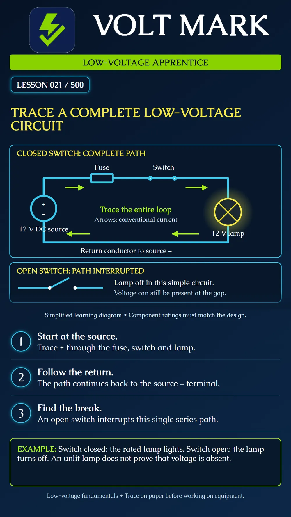
A working DC load needs an intended conducting path between the source terminals. In this simplified series example, follow source positive, fuse, closed switch, lamp, return conductor, source negative. The source supplies energy; the lamp converts electrical energy into light and heat.
Imagine a classroom trainer labeled Demonstrator A. Its drawing names the source terminals S+ and S−, the fuse F1, the switch SW1, and the lamp L1. All components have been selected by the instructor for that trainer. With the trainer disconnected, put a pencil on S+ and trace the drawing: S+ → F1 → SW1 → L1 → S−. Now the instructor hands you a second drawing where SW1 is open. Circle that gap. Your answer is not “the battery disappeared” or “the whole drawing is dead.” Your answer is “the intended series path is interrupted at SW1.”
The order is S+, F1, SW1, L1, S−. Outgoing wiring leads from positive through the control and load; return wiring completes the external route to negative. Closing SW1 joins its contacts. Opening it creates the shown break. A disconnected return also prevents the intended complete path. A direct source-terminal bridge is a short-circuit path, not an acceptable repair.
This is a reading exercise, not an installation drawing. It does not select conductor size, fuse rating, enclosure, terminal torque, battery capacity or a wiring method. Do not transfer it to a fire-alarm, access-control or security panel without the applicable manufacturer's actual design. Real systems may include several paths, electronics, supervision and standby power. “Return” is a function in this example. It does not mean that soil, building steel or a protective grounding conductor is the intended normal-current return. Follow the real equipment's terminal identification.
Q: What completes the external loop? A: The return connection to the other source terminal. Q: What do the green arrows represent? A: Conventional current direction in the external DC circuit. Q: Does an open switch remove the source voltage? A: No. Q: Does an unlit lamp establish that every part is safe to touch? A: No; lamp condition and circuit state are different questions. Q: What should be used to trace an actual control panel? A: Its correct manufacturer documentation and approved project drawings.
Stopping the trace at the load. Always locate the return connection too.
Start at positive. Follow the fuse, switch and lamp. Follow the return to negative. A closed switch completes this simple path; an open switch interrupts it. Darkness is an observation, not proof of absence of voltage.
SparkFun, What Is a Circuit? — circuit basics and open/short circuits: https://learn.sparkfun.com/tutorials/what-is-a-circuit The trainer names and paper exercise above are original illustrative teaching material.
Free study material for low-voltage apprentices. This is a national foundation course: requirements differ by state and by local jurisdiction, and a practice that is common in one place is not a rule everywhere. Nothing here is a licence, a certification, or authority to work unsupervised, and completing it does not count as apprenticeship hours or continuing-education credit. Check the codes adopted where you are working, the licensing authority for that work, and your employer's safety programme. VoltMark is not affiliated with, endorsed by, or sponsored by NFPA, OSHA, NICET, BICSI, FOA, or any state or local licensing authority.

Electrician licensing exam prep: practice questions, timed exam simulations, and step-by-step help finding every answer in the NEC.