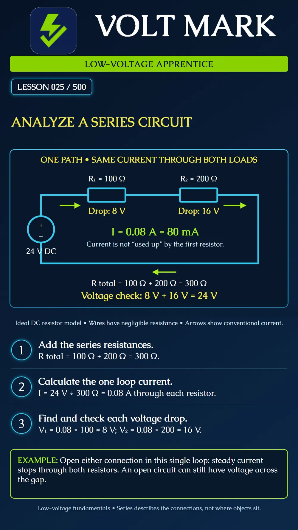
Identify a single series path, calculate its total resistance and current, then check the voltage drops across two resistors.
Components are in series when the same current passes through them in sequence without a branching path between them. For ideal series resistors, total resistance is the sum of their resistances. Each voltage drop equals that shared current times the individual resistance. In this one-source loop, the drops sum to the source voltage.
The fictional worksheet gives: Source: 24 V DC. R1: 100 Ω. R2: 200 Ω. Assumptions: ideal source, constant resistances and negligible wire resistance.
Step 1 — Add the resistances. R total = 100 Ω + 200 Ω = 300 Ω.
Step 2 — Calculate current using the complete loop resistance. I = 24 V ÷ 300 Ω = 0.08 A = 80 mA. The current is 80 mA through R1 and also 80 mA through R2. It does not become smaller after the first resistor.
Step 3 — Calculate the individual voltage drops. V1 = 0.08 A × 100 Ω = 8 V. V2 = 0.08 A × 200 Ω = 16 V.
Step 4 — Check the sum. 8 V + 16 V = 24 V, matching the source. The larger resistor has the larger voltage drop because the current is the same through both.
On a copy of this worksheet, rotate the page and trace the loop again. Nothing about the electrical relationship changes. Now imagine moving R2's drawn position to the bottom return line while retaining the same connections. It is still in the same series path. Physical appearance alone does not define a circuit.
A second worksheet specifies 12 V, R1 = 100 Ω and R2 = 300 Ω in series. Find total resistance, loop current and the two drops.
Answer:
R total = 400 Ω. I = 12 ÷ 400 = 0.03 A = 30 mA. V1 = 0.03 × 100 = 3 V. V2 = 0.03 × 300 = 9 V. Check: 3 V + 9 V = 12 V.
WHAT IF THE LOOP OPENS? A disconnected series connection interrupts this simple loop. With no other sources or paths in the model, steady current is zero through both resistors. The source can still maintain voltage across the open gap. “No current” is not the same statement as “no voltage.”
This is a resistor-network lesson, not permission to connect readers, cameras or other rated devices in series. Their internal electronics and required terminal voltages may make that inappropriate. An actual supervised security or fire-alarm circuit may contain contacts, end-of-line components and electronic monitoring. Its topology and permitted wiring come from the equipment documentation; the familiar word “loop” alone does not prove that the entire circuit matches this resistor model. The drawing also omits protection and switching for clarity. It is not a field installation drawing.
Q: Is the current split between R1 and R2? A: No; the same current passes through both in this series path. Q: Do unequal series resistors necessarily have equal voltage drops? A: No. Q: Which resistance is used to calculate the loop current? A: The total series resistance. Q: What proves the example's voltage-drop arithmetic is consistent? A: The drops add to the source voltage. Q: Does opening the loop prove zero voltage everywhere? A: No.
Using the full source voltage separately across each series resistor. First calculate the shared current from the total resistance.
Series means one path. Add the resistances, calculate the shared current, then calculate each voltage drop. In our example, 24 volts drives 80 milliamps through 100 ohms and 200 ohms. The drops are eight volts and sixteen volts, adding to twenty-four.
OpenStax, Physics, 19.2 Series Circuits: https://openstax.org/books/physics/pages/19-2-series-circuits The numerical examples, tracing exercise and questions above are original learning material.
Free study material for low-voltage apprentices. This is a national foundation course: requirements differ by state and by local jurisdiction, and a practice that is common in one place is not a rule everywhere. Nothing here is a licence, a certification, or authority to work unsupervised, and completing it does not count as apprenticeship hours or continuing-education credit. Check the codes adopted where you are working, the licensing authority for that work, and your employer's safety programme. VoltMark is not affiliated with, endorsed by, or sponsored by NFPA, OSHA, NICET, BICSI, FOA, or any state or local licensing authority.

Electrician licensing exam prep: practice questions, timed exam simulations, and step-by-step help finding every answer in the NEC.