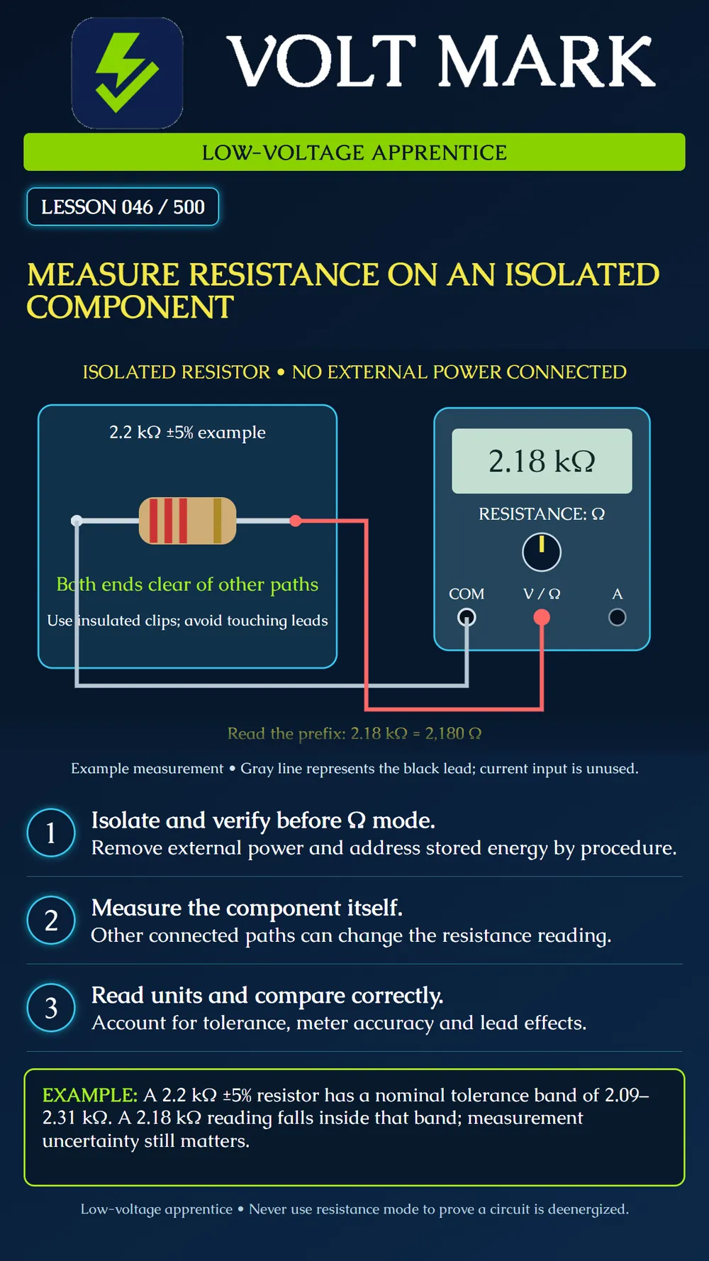
Measure a disconnected resistor, read its displayed unit correctly, and compare the result with a stated tolerance without mistaking an in-circuit reading for the component value.
Use an instructor-provided loose resistor and approved meter. The illustrated component is physically disconnected from any supply and other circuit paths. For equipment work, the employer's isolation and stored-energy procedure must be completed and verified before resistance mode is used. A switch position or an ohms reading does not prove that a circuit is deenergized.
A meter supplies a small internal test signal in resistance mode. External voltage interferes with the measurement and may damage equipment or create a hazard. Other components connected across the resistor can also affect the result. Removing power alone does not remove those parallel paths. This exercise uses a separate component so the learner can distinguish the resistor from a larger network.
For real assemblies, an approved procedure may require disconnecting a component lead or otherwise isolating the component. Do not cut or desolder installed equipment without authorization. Capacitors and other stored-energy sources need the appropriate procedure; do not improvise a discharge method.
Inspect the meter and leads. Identify COM and the designated resistance input, often combined with V and marked Ω. Put black in COM and red in that input. Select resistance and the appropriate range according to the manual. Verify that the function is resistance rather than merely a continuity beeper. An empty or unused current input is not part of this setup.
Check meter and lead behavior using the manufacturer's instructions. Lead and contact resistance become significant when measuring small resistance values. Use the instrument's documented compensation method where applicable; do not assume every reading should be adjusted by the same arbitrary amount.
Use approved insulated clips or probe technique on the loose component. Keep fingers from bridging its metal leads, particularly for high-resistance measurements. Establish stable contact without damaging the part. Observe the value and prefix. A display of 2.18 kΩ means 2,180 Ω, not 2.18 Ω.
A display such as OL can mean that the resistance exceeds the selected range, the connection is open, or contact has not been established. Consult the meter manual and check the setup before declaring the component failed. Changing to a suitable range may be necessary.
The resistor's nominal value is 2.2 kΩ and its tolerance is ±5%. Five percent of 2,200 Ω is 110 Ω. The nominal tolerance interval is 2,090 through 2,310 Ω. An illustrative reading of 2,180 Ω lies within that interval.
This comparison does not eliminate meter accuracy, resolution, contact effects, temperature, or an applicable acceptance rule. A result near a boundary needs the required uncertainty and decision process. A single resistance reading also does not demonstrate the component's power-handling capability or performance under every operating condition.
Record component identification, nominal value, tolerance, expected interval, measured value with prefix, meter range, and isolation method. Calculate the interval before looking at the measurement. Explain any discrepancy without changing the nominal value to fit the result.
On paper, two ideal 2.2 kΩ resistors are connected in parallel. Their combined resistance is 1.1 kΩ. This illustrates why measuring across a resistor still connected to other paths may not reveal that resistor's individual value.
Fluke, How to Measure Resistance: https://www.fluke.com.cn/学习/博客/技术博客/数字万用表/how-to-measure-resistance Fluke 12E User Manual, resistance and continuity precautions: https://assets.fluke.com/manuals/12e_____umeng0000.pdf Sources checked September 30, 2026. Follow the actual meter instructions.
Free study material for low-voltage apprentices. This is a national foundation course: requirements differ by state and by local jurisdiction, and a practice that is common in one place is not a rule everywhere. Nothing here is a licence, a certification, or authority to work unsupervised, and completing it does not count as apprenticeship hours or continuing-education credit. Check the codes adopted where you are working, the licensing authority for that work, and your employer's safety programme. VoltMark is not affiliated with, endorsed by, or sponsored by NFPA, OSHA, NICET, BICSI, FOA, or any state or local licensing authority.

Electrician licensing exam prep: practice questions, timed exam simulations, and step-by-step help finding every answer in the NEC.