Locate the correct low-voltage plan, interpret a stated scale, and distinguish a horizontal plan measurement from an installed cable route.
Read the sheet identifier, title, floor or area, revision, and issue status. Confirm that the drawing belongs to the current authorized set. A familiar room name does not establish that a sheet is current. Check referenced details and notes before using a dimension or device location.
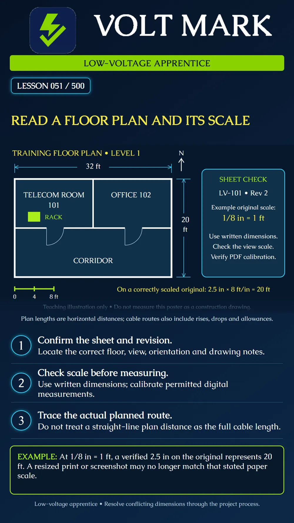
Find the north arrow or orientation reference and relate it to the building. Locate room numbers, walls, doors, telecommunications spaces, and the area covered by the work. Door swings and partitions help you understand access and layout, but they do not establish a cable pathway by themselves.
A plan scale expresses the relationship between a distance on the correctly reproduced drawing and a distance in the building. In the example, 1/8 inch represents 1 foot. Therefore one inch represents eight feet. An original measured length of 2.5 inches represents 2.5 × 8 = 20 feet.
A sheet can contain views drawn at different scales. A detail may be enlarged or marked not to scale. Use the scale assigned to the particular view. The teaching poster includes a proportional graphic scale for illustration, but it is not a construction drawing and should not be measured for field work.
Use stated dimensions and follow the project's instructions governing measurement from drawings. If a note prohibits scaling, do not scale a missing installation dimension as a substitute for clarification. Do not choose between conflicting written and measured dimensions by guessing. Raise the discrepancy through the designated project process.
A straight line between a rack and a device describes only a geometric separation. The permitted pathway may turn along a corridor, rise to a tray, pass through an approved sleeve, and drop to the device. The cable takeoff must account for the actual routed segments and the specified termination and service allowances. Do not invent a universal extra percentage and call it an exact installed length.
A correctly reproduced plan uses 1/8 inch = 1 foot. A horizontal route segment measures 3 inches. Its scaled horizontal length is 24 feet. The work also includes a documented 8-foot rise and a 6-foot drop. Those segments total 38 feet before any specified termination or service allowances. The route remains subject to the approved design and field conditions.
Now imagine the same drawing printed at half its intended linear size. That 24-foot segment measures only 1.5 inches on the reduced print. Reading it using the unchanged paper-scale note would incorrectly produce 12 feet. A reproduction check prevents this error.
Use an instructor-provided plan with explicit permission for scaled measurement. Record the sheet, revision, view, scale, calibration reference, and units. Identify a telecom room and a destination. Separate horizontal, vertical, and allowance items in the route record. Flag missing dimensions instead of silently assuming them.
Autodesk, Set Scale or Calibrate: https://help.autodesk.com/cloudhelp/ENU/Takeoff-Takeoff/files/Set_Scale.html Autodesk, About Setting the Plot Scale: https://help.autodesk.com/cloudhelp/2024/ENU/AutoCAD-Core/files/GUID-89604826-0B55-4994-8214-1CA93FA66985.htm VA Drawing Deliverable Requirements, drawing units and dimensions: https://www.cfm.va.gov/til/bim/DwgDelivRqmts.pdf Sources reviewed September 30, 2026. Project-specific drawing instructions control field use.
Free study material for low-voltage apprentices. This is a national foundation course: requirements differ by state and by local jurisdiction, and a practice that is common in one place is not a rule everywhere. Nothing here is a licence, a certification, or authority to work unsupervised, and completing it does not count as apprenticeship hours or continuing-education credit. Check the codes adopted where you are working, the licensing authority for that work, and your employer's safety programme. VoltMark is not affiliated with, endorsed by, or sponsored by NFPA, OSHA, NICET, BICSI, FOA, or any state or local licensing authority.

Electrician licensing exam prep: practice questions, timed exam simulations, and step-by-step help finding every answer in the NEC.