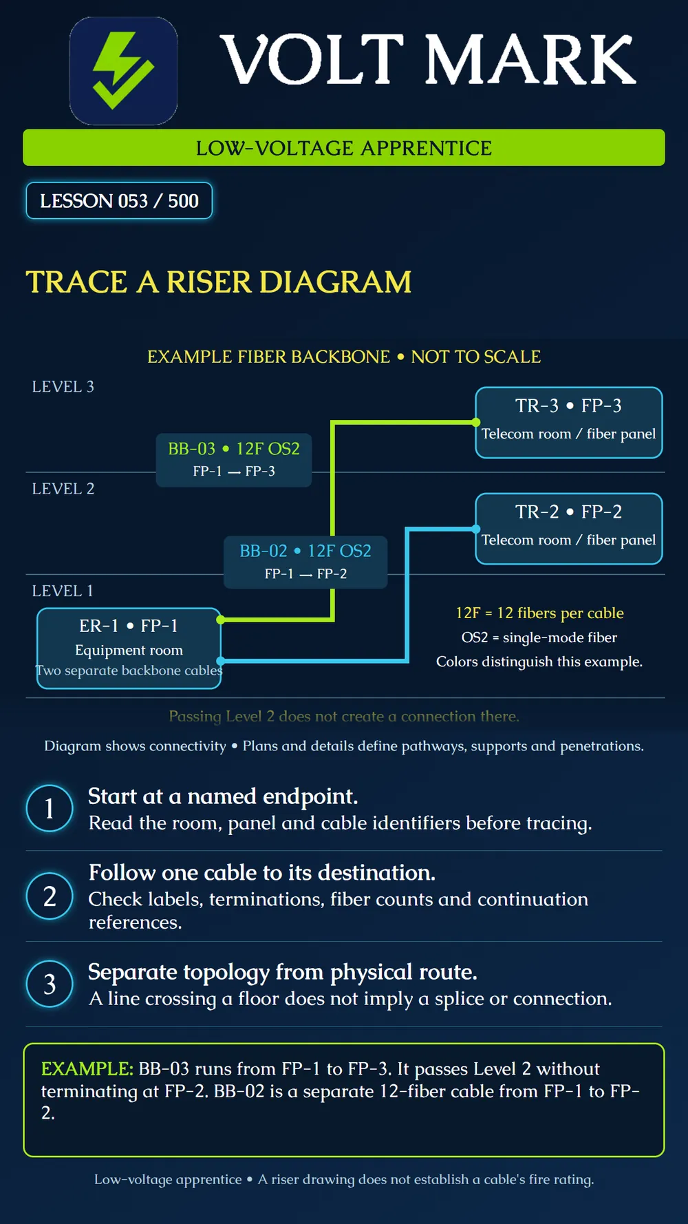
Follow one identified cable between its documented endpoints on a riser diagram while separating connectivity from physical installation details.
A riser diagram can organize equipment and connections by floor, building area, or system level. It helps show relationships that are difficult to see on a floor plan. It is commonly schematic; do not use its drawn line length as an installed cable length unless the drawing explicitly supports that use.
Confirm the sheet, revision, system, legend, and drawing notes. Locate the equipment rooms, telecommunications rooms, panels, and any continuation references. A diagram for one system does not describe every low-voltage system in the building.
Choose one cable identifier and find both endpoints. Follow the line without jumping to another nearby line. Read cable type, count, termination notes, and any splice or connector information supplied by the drawing and schedules. If a line continues on another sheet, carry its identifier to that referenced sheet.
A line passing a floor, crossing another line, or running beside a panel does not automatically establish a connection. Use the drawing's junction and termination conventions. If the intended connection is unclear, request clarification instead of inventing a splice.
Use the associated floor plans, pathway drawings, sections, and details to identify the actual route and installation requirements. Verify supports, sleeves, penetrations, and termination spaces through the approved design. A clean vertical line on a schematic does not mean the field route is unobstructed or that a cable can hang unsupported.
Likewise, a drawing called a riser does not establish that any particular cable jacket classification is suitable. Cable listing and permitted use depend on the actual location, installation, and applicable requirements. This lesson does not assign universal fire ratings or penetration methods.
Write the cable identifier, source room and panel, destination room and panel, specified cable type, fiber count, and referenced schedule or detail. Add fiber-position and port assignments only when the project documents provide them. Keep unresolved information visible.
An apprentice traces BB-03 and writes FP-1 → FP-2 → FP-3 because the cable line passes the second floor. Compare that statement with the drawing. It is incorrect: BB-03 terminates at FP-1 and FP-3 only in this example. FP-2 belongs to the separate BB-02 run.
A second apprentice orders twelve transceivers because the cable is labeled 12F. That conclusion is unsupported. The cable count does not establish the equipment or active link allocation. The correct next step is to consult the relevant schedule and approved equipment design.
On an instructor-provided diagram, trace one cable at a time with a removable markup. List its endpoints and every explicit connection. Compare the result with the cable schedule. Then identify which separate drawing would be needed to estimate the physical route. Report any mismatch.
FOA, Designing Premises Cabling Systems: https://www.thefoa.org/tech/ref/premises/design.html FOA, Fiber Optic Network Design, documentation: https://thefoa.org/tech/ref/basic/design.html Sources reviewed September 30, 2026. The diagram is an original simplified teaching example, not an installation design.
Free study material for low-voltage apprentices. This is a national foundation course: requirements differ by state and by local jurisdiction, and a practice that is common in one place is not a rule everywhere. Nothing here is a licence, a certification, or authority to work unsupervised, and completing it does not count as apprenticeship hours or continuing-education credit. Check the codes adopted where you are working, the licensing authority for that work, and your employer's safety programme. VoltMark is not affiliated with, endorsed by, or sponsored by NFPA, OSHA, NICET, BICSI, FOA, or any state or local licensing authority.

Electrician licensing exam prep: practice questions, timed exam simulations, and step-by-step help finding every answer in the NEC.