Trace a specified conductor from one named terminal to another and distinguish an explicit connection from an assumption based on number, color, or physical position.
Check the equipment models, connector designations, drawing revision, and applicable notes. A diagram for a similar-looking device may have a different pin assignment. Use the approved drawing and the actual manufacturers' instructions. Resolve discrepancies before connecting equipment.
A point-to-point drawing emphasizes which terminal connects to which other terminal. It may not reproduce the physical layout or exact wire route. A functional block diagram, floor plan, and terminal drawing answer different questions; use the correct document for the task.
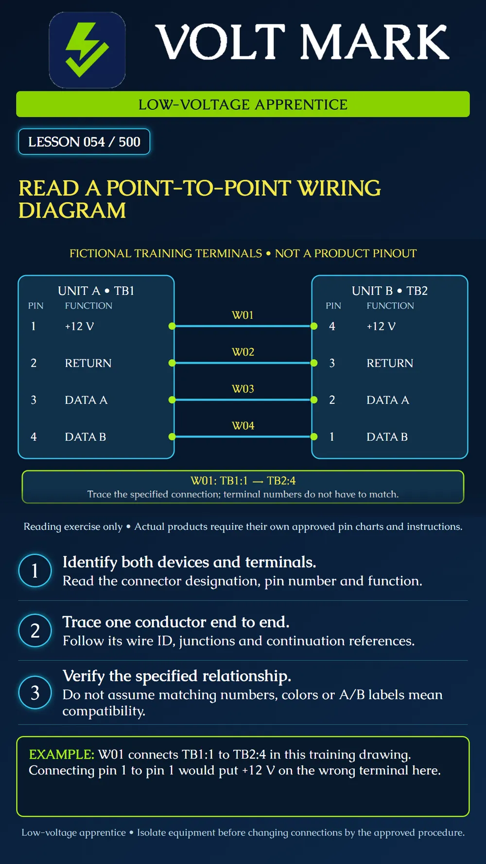
TB1:1 in the teaching example means terminal 1 of terminal block TB1 on Unit A. TB2:4 identifies terminal 4 of TB2 on Unit B. Keeping the connector designation with the terminal number prevents confusion when a device has several numbered connectors.
Read the function as well as the identifier. A marking such as COM can refer to different things depending on the circuit and device. A return terminal is not automatically protective earth. Likewise, A and B data labels require the specific interface instructions; do not infer universal polarity or compatibility from letters alone.
The diagram defines four fictional connections: W01: TB1:1 (+12 V) to TB2:4 (+12 V). W02: TB1:2 (RETURN) to TB2:3 (RETURN). W03: TB1:3 (DATA A) to TB2:2 (DATA A). W04: TB1:4 (DATA B) to TB2:1 (DATA B).
These assignments are invented for this reading exercise. They are not a product pinout or a complete installation design. Their purpose is to show that correct endpoint numbers need not match. The diagram's colors help readability and do not specify conductor insulation colors.
Follow the wire identifier along its line. Read any continuation reference, splice, terminal strip, or junction according to the legend. A visual crossing is not necessarily a connection, and a line passing near a symbol is not a termination. If the drawing omits information needed to make the connection, ask for clarification.
Cable identifiers and conductor identifiers serve different purposes. A cable may contain several individually identified conductors. Keep both where the project documentation requires them. Do not confuse a cable tag with a terminal number.
The drawing-reading exercise does not authorize live rewiring. Any connection change requires the approved isolation and stored-energy procedure, appropriate training, and the applicable device instructions. Cable construction, pair assignments, shielding, termination, power limits, and communication settings may be required elsewhere in the design. Do not treat a simplified four-line picture as a complete installation procedure.
A learner connects terminal 1 to terminal 1 because the numbers match. In this example, Unit A terminal 1 is +12 V while Unit B terminal 1 is DATA B. The proposed connection is wrong. The correct paper trace is W01 from TB1:1 to TB2:4.
A second learner memorizes that data A always connects to a terminal labeled A. Real manufacturers can specify different mappings for particular product combinations. The learner must follow the documented relationship for the actual devices rather than copying this fictional example.
On a disconnected training setup or on paper, make a connection list containing device, connector, terminal, function, wire ID, and destination. Compare every row with the drawing. Have the instructor check the list before any authorized assembly. Record unresolved differences instead of changing the drawing to match a guess.
Axis A4030-E Reader manual, device-specific wiring table: https://help.axis.com/en-us/axis-a4030-e Axis A4020-E Reader manual, controller-specific wiring mappings: https://help.axis.com/en-us/axis-a4020-e Source review: September 30, 2026. These references illustrate why the actual product combination and pin chart matter; neither is represented by the fictional diagram.
Free study material for low-voltage apprentices. This is a national foundation course: requirements differ by state and by local jurisdiction, and a practice that is common in one place is not a rule everywhere. Nothing here is a licence, a certification, or authority to work unsupervised, and completing it does not count as apprenticeship hours or continuing-education credit. Check the codes adopted where you are working, the licensing authority for that work, and your employer's safety programme. VoltMark is not affiliated with, endorsed by, or sponsored by NFPA, OSHA, NICET, BICSI, FOA, or any state or local licensing authority.

Electrician licensing exam prep: practice questions, timed exam simulations, and step-by-step help finding every answer in the NEC.