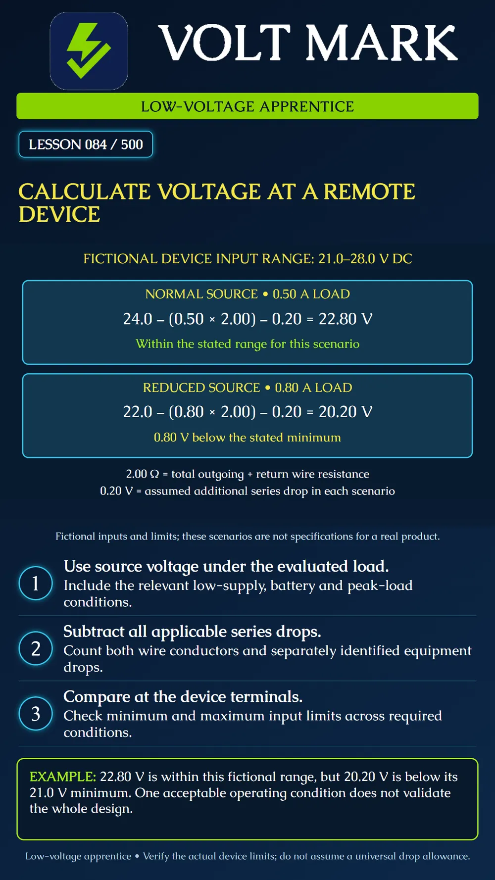
Evaluate the voltage available at a remote device for stated operating conditions and compare it with that device's input limits.
Use voltage at the supply output feeding the evaluated route under the relevant load. A nominal "24 V" label is not evidence of the voltage available in every condition. Consider the actual supply's regulation, applicable standby operation and load state.
The Altronix AL400ULX guide illustrates manufacturer-specific output checks under load and battery-backup behavior. It does not establish the fictional values used here. Use the exact installed model's documentation and revision when evaluating a real system.
For a simple dedicated two-wire branch: Device voltage = source voltage - wire-loop drop - other series drops. Wire-loop drop = current x total outgoing-and-return wire resistance.
Speco's paired-wire guidance counts both the feed and return. If loop resistance is already supplied, do not double it again. Keep connection, protection and switching drops separate only when they are not already included in the chosen resistance or measured drop.
Device permitted input: 21.0 to 28.0 V DC. Total wire-loop resistance at the evaluated condition: 2.00 ohms. Other series voltage drop: assumed 0.20 V in each scenario. Normal source: 24.0 V with 0.50 A load. Reduced source: 22.0 V with 0.80 A load.
The current values are assumed operating-point data. The 0.20 V allowance is a given for this exercise, not a typical relay or fuse drop. Real component drops can change with current and temperature. The two scenarios are separate conditions, not simultaneous loads.
Wire drop = 0.50 x 2.00 = 1.00 V. Device voltage = 24.0 - 1.00 - 0.20 = 22.80 V. 22.80 V is between the fictional minimum 21.0 V and maximum 28.0 V. Distance above the minimum = 22.80 - 21.0 = 1.80 V.
Wire drop = 0.80 x 2.00 = 1.60 V. Device voltage = 22.0 - 1.60 - 0.20 = 20.20 V. Shortfall below minimum = 21.0 - 20.20 = 0.80 V. This condition does not meet the stated input requirement. It needs design resolution; the normal-source result does not cancel it.
Evaluate high-source and low-load conditions against the maximum device input. Raising source voltage to fix a distant device can expose another device to too much voltage. Changes require checking the whole affected design and manufacturer limits.
Do not describe a result exactly at a limit as comfortable margin. Account for relevant tolerances and design requirements. No universal percentage drop allowance is established by this lesson.
A constant-power device may draw more current as its input voltage falls. A startup pulse can be brief but significant. Shared wiring carries the combined downstream current on common segments. Use actual load behavior and segment currents rather than forcing every system into this simple model.
Document the calculation inputs and their evidence. Field validation, when authorized and performed by suitably trained personnel, should evaluate the relevant operating condition at the device terminals. This lesson does not instruct an apprentice to probe energized enclosures or interrupt active services.
Device ID, exact model and input range: Source ID and evaluated voltage: Operating scenario and current: Loop resistance, temperature basis and source: Other drops and inclusion boundaries: Calculated device-terminal voltage: Comparison with both input limits: Tolerance/startup/standby checks outstanding: Reviewer, revision and disposition:
Speco Technologies - How to calculate DC voltage drop for long wire runs: feed-and-return voltage-drop basis. https://info.specotech.com/how-to-calculate-dc-voltage-drop-for-long-wire-runs Altronix - AL400ULX Installation Guide: output testing under load, battery operation and warning about improper/high voltage. https://www.altronix.com/library/pdf/installation_instructions/AL400ULX.pdf
All numerical inputs and device limits in this exercise are fictional. A calculation does not establish overall code compliance or authorize equipment changes.
Free study material for low-voltage apprentices. This is a national foundation course: requirements differ by state and by local jurisdiction, and a practice that is common in one place is not a rule everywhere. Nothing here is a licence, a certification, or authority to work unsupervised, and completing it does not count as apprenticeship hours or continuing-education credit. Check the codes adopted where you are working, the licensing authority for that work, and your employer's safety programme. VoltMark is not affiliated with, endorsed by, or sponsored by NFPA, OSHA, NICET, BICSI, FOA, or any state or local licensing authority.

Electrician licensing exam prep: practice questions, timed exam simulations, and step-by-step help finding every answer in the NEC.