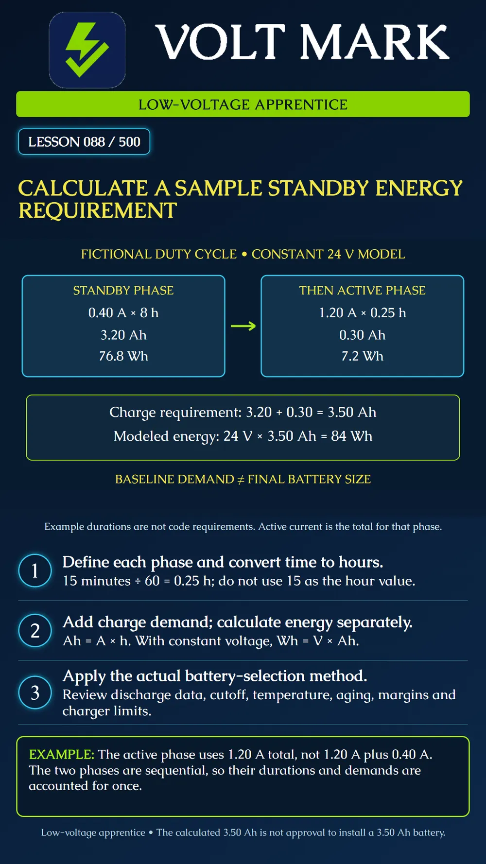
Calculate a baseline charge and energy demand for a stated duty cycle, then identify the additional work needed to select a battery.
A fictional system operates for 8 hours in standby at 0.40 A total, followed by 15 minutes in an active mode at 1.20 A total. The phases do not overlap. Each current includes all demand at the evaluated boundary for that phase, including system electronics.
Assume a constant 24 V at that boundary for the energy arithmetic. No converter losses or additional battery-side overhead are included. These are teaching assumptions, not a real battery discharge model. The example's 8-hour and 15-minute durations are not national code requirements.
15 minutes /60 minutes per hour = 0.25 h. Total elapsed exercise time = 8 + 0.25 = 8.25 h.
Standby: 0.40 A x 8 h = 3.20 Ah. Active: 1.20 A x 0.25 h = 0.30 Ah. Total: 3.20 + 0.30 = 3.50 Ah.
The active current is the full current during that phase. Do not add the standby current to it again. If a source document instead gives an incremental active current, resolve that distinction before calculating.
Ampere-hours measure charge; watt-hours measure energy. They are not interchangeable units. At the assumed constant 24 V: Standby energy = 24 x 0.40 x 8 = 76.8 Wh. Active energy = 24 x 1.20 x 0.25 = 7.2 Wh. Total modeled energy = 76.8 + 7.2 = 84.0 Wh. Cross-check: 24 V x 3.50 Ah = 84 Wh.
If voltage and current vary, evaluate the appropriate time segments or use an appropriate energy model. Multiplying a battery's nominal voltage by Ah provides an approximation, not a guarantee of usable energy down to the system's cutoff voltage.
If the currents are device-side currents behind a converter, account for conversion losses and other battery-side demands using the actual equipment method. Do not add currents from different voltage rails as if they were all measured at the same battery voltage. State what every value includes so internal electronics are neither omitted nor counted twice.
The Altronix ACM-series worksheet shows a manufacturer method that separately accounts for internal and load currents, operating durations and a model-specific sizing factor. Its factor and capacity limits belong to that equipment and worksheet. Do not transplant them into every application.
Power-Sonic's PG-12V100 data sheet illustrates that rated capacity depends on discharge duration and endpoint voltage. A battery's label does not promise the same usable capacity at every discharge rate. Review the selected battery's discharge data, required cutoff, temperature and applicable aging or reserve requirements.
The final selection also needs charger compatibility, permitted capacity, recharge requirements, enclosure suitability and system approval. A physically larger battery does not automatically solve all these constraints.
Use the actual system type, adopted rules, approved design and manufacturer instructions to determine standby and active/alarm durations. Fire alarm, intrusion, access control and other systems do not share one universal standby rule. This lesson teaches the calculation method without prescribing a nationwide duration.
1.0.50 h. 2.3.20 +(1.20 x 0.50) = 3.80 Ah;24 x 3.80 = 91.2 Wh. 3.(0.50 x 8) + 0.30 = 4.30 Ah;24 x 4.30 = 103.2 Wh. These remain baseline exercise results, not battery sizes.
System and evaluated power boundary: Source of required durations: Phase, total current and duration: Included internal and accessory loads: Charge demand per phase: Voltage/energy assumptions: Losses and unresolved battery-side demand: Applicable sizing method and factors: Discharge/cutoff/temperature evidence: Charger and capacity constraints: Reviewer and disposition:
Altronix - ACM Series Installation Guide, AL1024ULACM battery-size worksheet: distinct currents/durations and equipment-specific selection method. https://www.altronix.com/library/pdf/installation_instructions/ACMseries.pdf Power-Sonic - PG-12V100 data sheet, version 1.2 dated August 18, 2026: capacity ratings and discharge endpoint information. This product is not selected for the example. https://www.power-sonic.com/wp-content/uploads/datasheets/pg-12v100.pdf
All example currents, durations and constant-voltage assumptions are fictional.
Free study material for low-voltage apprentices. This is a national foundation course: requirements differ by state and by local jurisdiction, and a practice that is common in one place is not a rule everywhere. Nothing here is a licence, a certification, or authority to work unsupervised, and completing it does not count as apprenticeship hours or continuing-education credit. Check the codes adopted where you are working, the licensing authority for that work, and your employer's safety programme. VoltMark is not affiliated with, endorsed by, or sponsored by NFPA, OSHA, NICET, BICSI, FOA, or any state or local licensing authority.

Electrician licensing exam prep: practice questions, timed exam simulations, and step-by-step help finding every answer in the NEC.