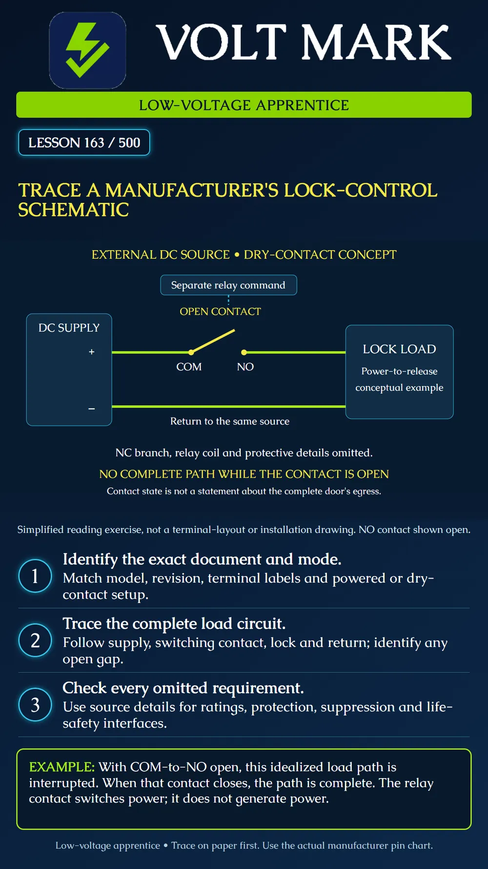
Read a manufacturer lock-control drawing by identifying its power source, switching contacts, load and return. Distinguish a functional schematic from a physical terminal layout and from the complete opening sequence.
Use Axis Communications, AXIS A16 Network Door Controller Series, Electrical wiring drawings, November 2024, PDF page 9 of 10, "Possible relay options for A-line products." The source presents powered relay arrangements and an externally powered arrangement. Compare its labels with the exact controller manual and project pin chart. The lesson poster is an original functional abstraction, not a reproduced manufacturer drawing. The PDF's text was available during production; its web screenshot service failed. Accordingly, the poster does not claim to reproduce physical jumper positions or terminal geometry. [1]
Start at the title block and application notes. Verify the product model and document revision. Find the contact-state convention and the intended power configuration before following a line. A contact labelled COM is the common terminal of a switching contact; it is not automatically the supply negative. NO means normally open relative to the defined relay reference state, not "the door is normally open."
In the A1610 documentation, fitting a relay power jumper connects a selected internal voltage to relay COM. Without that powered connection, the switching contacts can serve an externally supplied circuit. This distinction matters: an output that supplies power and a dry contact that merely switches a separate source are different arrangements. Refer to the exact product instructions and generated pin chart; do not combine internal and external sources because both are marked positive. [1,2]
Trace the poster as a reading exercise. External supply positive runs to COM. The switch blade is shown separated from NO. NO continues toward the conceptual lock load; the load's return runs back to the same external supply negative. With the illustrated gap open, the idealized load loop is interrupted. Closing COM to NO completes that path, assuming the source and the remaining circuit are intact. There is no numerical voltage or current assignment in this drawing.
The lock is a conceptual power-to-release load. Energizing it represents entry release for this exercise, not a universal rule for every lock. Its de-energized mechanical behavior and the complete opening's egress must be established separately. The schematic omits the unused NC branch and the relay coil. The dashed command indicator is explanatory; it is not an extra field conductor connected to a load terminal.
Read what the simplified drawing leaves out. Actual instructions govern permitted voltage, steady and startup load, contact ratings, protective devices, wire requirements and transient suppression. The A1610 manual discusses flyback protection for applicable lock loads; use the specific controller and lock instructions to determine what is required and compatible. A generic diode is not a universal answer for every AC, DC or electronically controlled lock. [2] Also find door-position and lock-monitor circuits where provided. They supply information and must not be mistaken for the lock's power-return conductor. Required release or life-safety interfaces belong in the coordinated design. Their absence from this teaching diagram is not permission to omit them.
A learner traces positive to COM, then jumps directly from the relay symbol to supply negative. Ask them to point to the load in that trace. The missing load shows that the path was not followed correctly. A second learner sees the relay-command event in a log and writes "voltage reached the lock." That log proves a command, not the actual load voltage or mechanical release. Identify the separate evidence needed before making either claim. Do not improvise live measurements from this paper exercise.
Work with the manufacturer's drawing and a de-energized, isolated training diagram or trainer approved by the instructor. Mark source positive in one color, the switched path in another and the return in a third. Circle each contact gap and label the state depicted. Then map each function to the actual manufacturer's terminal labels on paper. Have the instructor select one alternate documented configuration. Explain which assumptions change, especially source selection and contact choice. Do not move jumpers or connect a live opening as part of this reading exercise. Any later installation or testing requires its own authorized procedure.
Retain document title and revision, page, model, power mode, depicted contact state, source/load/return trace, unresolved questions and relevant project drawing reference. If the physical label differs from the drawing, stop treating the drawing as a confirmed match and resolve the discrepancy.
Answer: No; it is the relay contact's common connection.
Answer: The open COM-to-NO contact gap.
Answer: No.
Answer: No; use the exact manufacturer document and pin chart.
Answer: No; the complete opening and its required sequence need separate review.
[1] Axis Communications, AXIS A16 Network Door Controller Series, Electrical wiring drawings, November 2024, PDF page 9. https://www.axis.com/dam/public/be/12/f7/axis-a16--electrical-wiring-drawings-en-US-457256.pdf [2] Axis Communications, AXIS A1610 Network Door Controller, Relay connector and Relay power jumper sections. https://help.axis.com/en-us/axis-a1610
Free study material for low-voltage apprentices. This is a national foundation course: requirements differ by state and by local jurisdiction, and a practice that is common in one place is not a rule everywhere. Nothing here is a licence, a certification, or authority to work unsupervised, and completing it does not count as apprenticeship hours or continuing-education credit. Check the codes adopted where you are working, the licensing authority for that work, and your employer's safety programme. VoltMark is not affiliated with, endorsed by, or sponsored by NFPA, OSHA, NICET, BICSI, FOA, or any state or local licensing authority.

Electrician licensing exam prep: practice questions, timed exam simulations, and step-by-step help finding every answer in the NEC.