Under supervision, prepare and terminate a reader cable on an isolated training setup using the actual reader and controller documents. Produce a checked termination record before any supervised energization.
Use a dedicated bench trainer with no connection to a live building door, lock release, fire-alarm interface or production access system. The instructor selects compatible equipment, cable and protected power arrangements and establishes the isolation procedure. Account for every source, including PoE, separate DC feeds and backup power where present. Turning off software does not isolate electrical power. Follow the site's verification procedure before handling conductors.
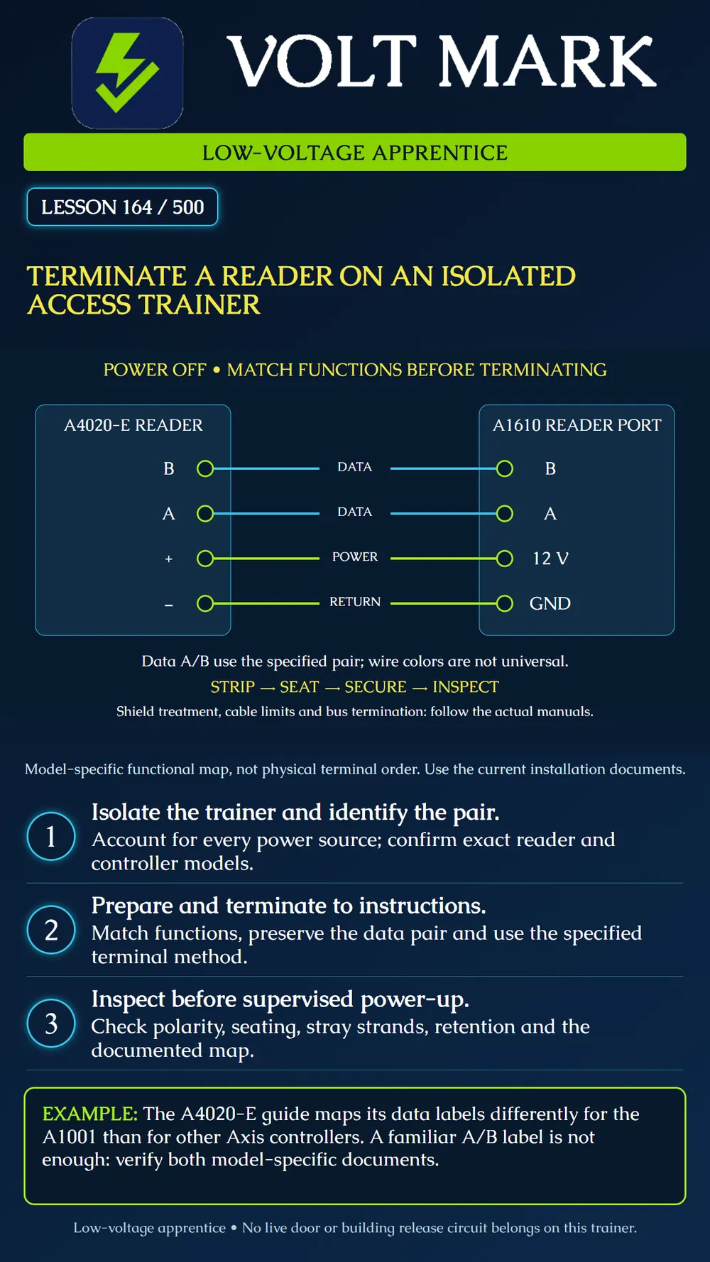
The diagram is a functional mapping for an AXIS A4020-E reader and AXIS A1610 reader port. It shows reader B to controller B, reader A to controller A, reader positive to the reader supply's 12 V output, and reader negative to its GND return. It is not the physical connector order. The A4020-E wiring table explicitly uses a different A/B mapping for the older A1001. This is why both exact model documents must be checked rather than assuming identical letter labels always connect together. [1]
The A1610 documentation identifies reader-connector functions and a shared reader power budget. Use its current limits and cable requirements for the actual configuration. A terminal marked 12 V does not mean unlimited available current, and the reader connection is not interchangeable with a lock relay connector. Identify the correct connector before preparing the cable. [2]
Place the selected documents and the instructor's trainer diagram beside the unpowered trainer. Record model numbers and document revisions. Make a connection worksheet with reader function, controller function, conductor identifier and inspection result. Assign labels by function rather than relying on remembered insulation colors. Confirm the selected cable meets the documented interface and power requirements. Preserve the intended twisted data pair. Plan enough working length to avoid tension while keeping the cable organized. Identify the required shield/drain treatment from the specific instructions; do not improvise a universal grounding arrangement.
Use the correct stripping tool and the manufacturer's specified strip length. Remove insulation without nicking or cutting strands. If preparation damages the conductor, remake that end rather than hiding the damage inside the terminal. Keep unused conductors individually insulated and secured as required. Insert the conductor into the intended terminal using the specified preparation and connector method. Confirm that the clamping element captures conductor, not insulation, and that exposed strands cannot bridge adjacent terminals. Use the specified tightening method and torque where applicable. Do not assume every connector accepts ferrules, solder-tinned ends or multiple conductors. Support the cable with the trainer's intended strain relief so handling the cable does not pull on the terminal. Label both ends. Follow the actual device instructions for any terminal-block seating and reader mounting steps.
Have the instructor compare the completed worksheet with the physical terminations. Check supply polarity, data mapping, correct connector, conductor seating, stray strands, unused wires, cable support and relevant shield treatment. Record any mechanical or visual defects before proceeding. Any continuity or short-circuit checks must use an instructor-approved method that accounts for connected electronics; do not apply an insulation-resistance tester to connected reader electronics. Address and bus-termination settings must also match the planned trainer topology. This lesson focuses on physical termination. Reader communication and Secure Channel configuration are developed in Lesson 165.
A learner copies a wiring note from an A1001 exercise onto an A1610 trainer because both products use A/B labels. The instructor notices the model mismatch during the paper comparison. Correct the worksheet from the actual reader/controller documents before connecting or energizing anything. This catches the error without treating trial-and-error live rewiring as a diagnostic method.
After the inspection is complete, the instructor controls first energization using the approved bench procedure. Observe only the checks assigned for the lesson, such as the documented reader power indication. An illuminated reader is not proof of correct communications or encryption. Record what was observed and leave untested functions explicitly pending. Isolate the trainer again before correcting any conductor termination.
Retain trainer ID, reader/controller models, document revisions, cable identification, the functional map, power-isolation verification, visual inspection findings, corrections, instructor check and limited energization observations. Do not record real credentials, encryption keys or production passwords in the exercise sheet.
Answer: No; it shows functional relationships for the named model pair.
Answer: Color assignments are not universal and do not establish terminal function.
Answer: Only the observed power-related behavior; communication and security still need verification.
Answer: Re-establish the trainer's required isolation and verification.
Answer: To find mapping, polarity and workmanship errors without relying on a powered trial.
[1] Axis Communications, AXIS A4020-E Reader, Wiring section. https://help.axis.com/en-us/axis-a4020-e [2] Axis Communications, AXIS A1610 Network Door Controller, Reader connector specifications. https://help.axis.com/en-us/axis-a1610
Free study material for low-voltage apprentices. This is a national foundation course: requirements differ by state and by local jurisdiction, and a practice that is common in one place is not a rule everywhere. Nothing here is a licence, a certification, or authority to work unsupervised, and completing it does not count as apprenticeship hours or continuing-education credit. Check the codes adopted where you are working, the licensing authority for that work, and your employer's safety programme. VoltMark is not affiliated with, endorsed by, or sponsored by NFPA, OSHA, NICET, BICSI, FOA, or any state or local licensing authority.

Electrician licensing exam prep: practice questions, timed exam simulations, and step-by-step help finding every answer in the NEC.