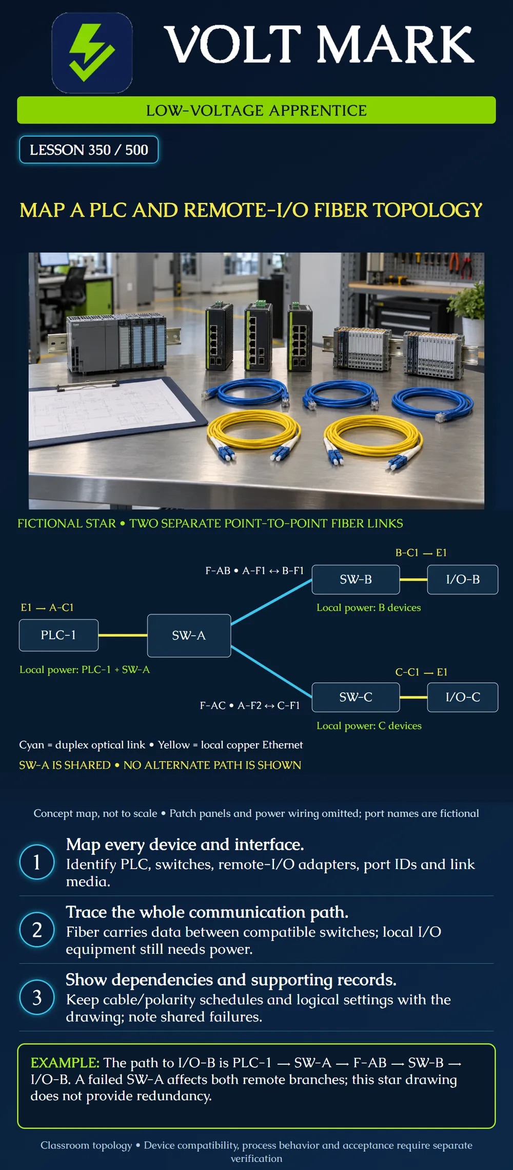
Trace a PLC-to-remote-I/O communication path through a labeled fiber topology and identify the supporting physical, logical and power records needed to make the drawing useful.
A PLC is a programmable logic controller. Remote I/O connects process input/output functions to a controller through the chosen compatible communication system. The drawing in this lesson uses a fictional switched Ethernet star. It is not a diagram of the older proprietary network sometimes called Remote I/O. Rockwell Automation’s networking guidance includes switch-level star arrangements connecting controllers and distributed I/O [1]. Its current product material also shows that some remote-I/O families have copper or optical interface options and topology support that depends on the selected equipment [2]. This does not make every controller and adapter interchangeable.
PLC-1 has a compatible copper Ethernet port E1. SW-A, SW-B and SW-C are managed switches with the required supported interfaces. I/O-B and I/O-C are compatible remote-I/O adapters with copper Ethernet port E1. The two switch-to-switch connections use compatible duplex optical interfaces and two glass strands per link. Exact product choices, wavelengths, fiber grades and loss limits are not specified by the drawing; they must be established in the design packet. The assumed control protocol is EtherNet/IP for this exercise. The drawing alone does not establish device profiles, controller support, firmware compatibility, timing or functional safety.
PLC-1 E1 connects by local copper Ethernet to SW-A port A-C1. SW-A A-F1 connects over fiber link F-AB to SW-B B-F1. SW-B B-C1 connects by local copper Ethernet to I/O-B E1. SW-A A-F2 connects over separate fiber link F-AC to SW-C C-F1. SW-C C-C1 connects by local copper Ethernet to I/O-C E1. These port IDs are fictional documentation labels, not manufacturer interface names. The arrows in the text identify endpoints; Ethernet communications are bidirectional.
For branch B, start at PLC-1, pass through SW-A and its A-F1 optical interface, follow F-AB to SW-B, then follow B-C1 to I/O-B. For branch C, start at the same PLC and switch, use A-F2 and F-AC, then SW-C and its local copper connection to I/O-C. Do not draw a passive split in either optical link. Each branch has its own switch port and point-to-point optical connection.
The lime notes identify local power for the devices at A, B and C. They do not show wiring, voltage, grounding or backup-power arrangements. The optical data links do not power the remote switches or I/O adapters. In a real packet, identify the device supply requirements and source records separately. Do not infer PoE capability or a supply voltage from an Ethernet port.
For F-AB, assign fictional cable AB strand 01 to A transmit/B receive, and AB strand 02 to B transmit/A receive. For F-AC, assign fictional cable AC strand 01 to A transmit/C receive, and AC strand 02 to C transmit/A receive. That is two optical links, four optical interfaces and four working strand assignments across two cables. This does not specify the total installed cable strand count; reserves and unassigned strands need their own records. Patch panels, splices, connector types and measured route lengths are omitted from the concept map. A construction-ready schedule must add them and preserve end-to-end polarity.
The physical map answers what connects to what, by which medium and port. The logical record identifies the approved device addresses, network segmentation, protocol settings and controller-to-I/O relationships. A correct cable drawing cannot prove the logical configuration is correct. Conversely, a device appearing in a controller project does not establish that the field cabling matches the drawing. Keep the topology revision linked to the parts list, cable schedule, logical configuration baseline and acceptance records.
If F-AB is unavailable, branch B loses its only illustrated network path. Branch C retains its illustrated physical path, subject to the remaining devices and configuration functioning. If SW-A fails, both branches lose their illustrated controller path. The PLC-to-SW-A copper connection is another shared dependency. No alternate route or redundant controller is shown. Two remote branches do not mean that either branch has two paths. Process responses to communication loss are outside this drawing and require the responsible control-system design.
Check device identifiers, cabinet locations, port labels, media legend, link IDs, strand/polarity schedule references, local power references, logical configuration reference, shared dependencies, revision and reviewer. Mark missing product or interface data as unresolved. Do not convert a conceptual sketch into an approved installation by adding guessed part numbers.
Mistake: Reading the two branches as redundant paths for each I/O cabinet. Correction: Trace each branch separately and mark SW-A and its PLC connection as shared dependencies; no alternate path is drawn.
Mistake: Treating one optical line as a passive split feeding both cabinets. Correction: Retain the separate A-F1/F-AB and A-F2/F-AC point-to-point links and their endpoint ports.
Mistake: Using the physical drawing as proof of controller-to-I/O compatibility. Correction: Link it to the exact adapter, firmware, logical configuration and application requirements before closing the review.
[1] Rockwell Automation, The OEM Guide to Networking: https://literature.rockwellautomation.com/idc/groups/literature/documents/rm/enet-rm001_-en-p.pdf Primary indexed switch-level star example used only for the stable topology concept, not historical product recommendations. [2] Rockwell Automation, FLEX 5000 I/O Modules: https://www.rockwellautomation.com/en-us/products/hardware/allen-bradley/i-o/in-cabinet-distributed-i-o/5094-flex-5000-i-o.html.html Primary indexed product text inspected for the existence of copper/optical interface options and equipment-dependent topology support. No named FLEX product is assigned to this fictional drawing. Accessed 2026-10-01. All device IDs, port IDs, link assignments and cases are original teaching material.
Texas journeyman, 15 questions, scored by topic against the 70% mark. No card, and no account needed to start.
Free study material for low-voltage apprentices. This is a national foundation course: requirements differ by state and by local jurisdiction, and a practice that is common in one place is not a rule everywhere. Nothing here is a licence, a certification, or authority to work unsupervised, and completing it does not count as apprenticeship hours or continuing-education credit. Check the codes adopted where you are working, the licensing authority for that work, and your employer's safety programme. VoltMark is not affiliated with, endorsed by, or sponsored by NFPA, OSHA, NICET, BICSI, FOA, or any state or local licensing authority.

Electrician licensing exam prep: practice questions, timed exam simulations, and step-by-step help finding every answer in the NEC.