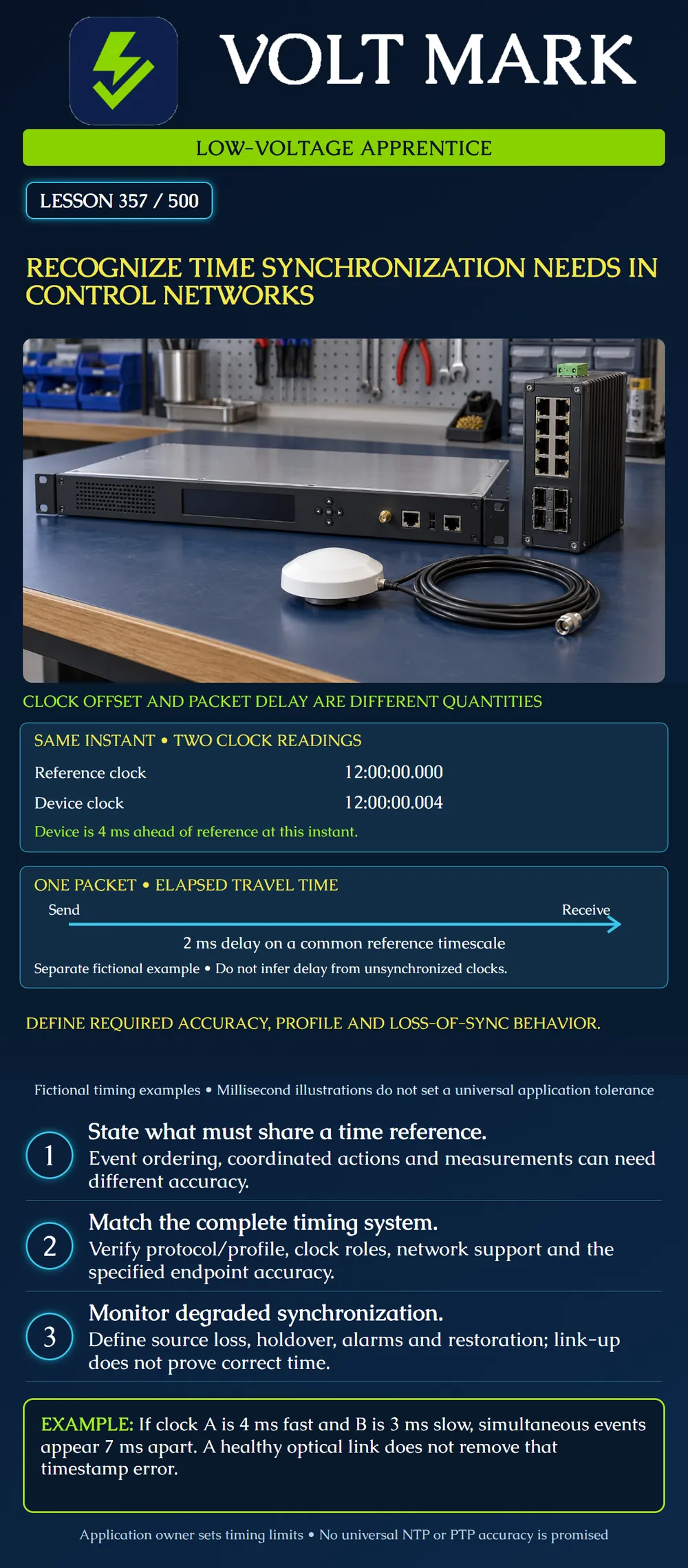
Distinguish clock offset from packet delay, identify application-specific synchronization requirements and recognize the evidence needed when time quality degrades.
The upper example compares two clock readings at the same actual instant. The reference reads 12:00:00.000 and the device reads 12:00:00.004. The device is four milliseconds ahead. The lower example follows a packet from sending to receiving. Its elapsed delay is two milliseconds on a common reference timescale. It is a separate fictional example, not a calculation from the two clocks above. Subtracting timestamps from unsynchronized devices can mix actual travel time with clock offset. A link indicator does not tell you either quantity accurately.
An application may need event timestamps that can be compared across devices, coordinated actions or time-aligned measurements. Those needs do not necessarily have the same accuracy requirement. The owner must state the required time reference, endpoint error limit, operating conditions and evidence method. Avoid selecting a universal tolerance merely because the network carries control traffic or uses fiber.
PTP, the Precision Time Protocol, uses clock roles and configuration choices that must match the intended system. Cisco’s industrial-switch guidance distinguishes profiles and modes such as boundary and transparent clock behavior [1]. Exact support depends on hardware and software. NIST’s NTP research identifies network delay asymmetry as an important source of time-transfer error [2]. The general lesson is to evaluate the actual timing path and measurement uncertainty rather than assume the protocol name establishes accuracy. No PTP or NTP accuracy guarantee is supplied here.
Identify the authoritative time source and how time reaches the endpoint. For a PTP design, verify required profile, domain, delay mechanism and supported clock roles against the exact configuration. A boundary clock synchronizes upstream and supplies timing downstream. A transparent clock accounts for relevant forwarding delay in timing information. These functions are not interchangeable labels to apply to every switch. The project must establish how the selected devices implement the required behavior. A supported optical port alone does not establish supported timing functions.
Clock A is four milliseconds fast relative to the common reference. Clock B is three milliseconds slow. Two events occur simultaneously in actual time. A’s reported timestamp is seven milliseconds later than B’s: +4 − (−3) = 7 ms. A log viewer could therefore suggest an order that did not exist. This example shows why clock-quality evidence matters when comparing event records. It does not specify the accuracy required for any real process.
A packet is sent when the reference time is 0 ms and arrives when reference time is 2 ms. The receiving device’s clock is four milliseconds fast. Its receive timestamp is therefore 6 ms. Subtracting the sender’s 0 ms timestamp from that uncorrected reading would report 6 ms, although the actual packet delay is 2 ms. This is simple classroom arithmetic, not a complete NTP/PTP estimation algorithm.
Document how a device indicates source loss and what its application does with degraded time. Some systems continue using a local oscillator in holdover; their error can grow while disconnected from the reference. Do not assume that data forwarding stops when timing fails, or that normal Ethernet traffic proves synchronization remains acceptable. The status, alarms and required response must be specified separately.
Assume a fictional clock begins holdover with an error magnitude bounded by 1 ms. Its supplied simplified model adds up to 0.2 ms of error per minute in the unfavorable direction. After ten minutes, the bound is 1 + 0.2 × 10 = 3 ms. If the fictional application allows at most 2 ms, that model reaches the limit after five minutes and exceeds it afterward. Real holdover behavior depends on the actual clock and conditions; this invented linear model is not a product specification. Document the required source-loss alarm and application response rather than relying on an assumed drift value.
Measure or otherwise verify the specified endpoint timing error using an appropriate reference and method. Record the clock state, profile/configuration, source identity, topology, load and uncertainty. Include agreed source-loss and restoration cases. A normal status flag is useful evidence, but it does not replace the endpoint accuracy check required by the project. Perform any tests under the approved control-system plan. Do not change time sources or clock settings on live systems for this classroom exercise.
Record application purpose; reference timescale; maximum permitted endpoint error; normal and degraded conditions; time source; protocol/profile and device roles; network/path assumptions; measurement method and uncertainty; source-loss indication; holdover evidence; restoration behavior; owner and acceptance record.
Mistake: Calling an uncorrected 6 ms timestamp difference the packet's actual delay. Correction: Account for the receiving clock's +4 ms offset; the example's actual reference-time delay is 2 ms.
Mistake: Assuming a supported PTP label settles profile and clock-role compatibility. Correction: Verify the exact profile, domain, delay mechanism, device role and software support required by the project.
Mistake: Treating continued data forwarding as proof that holdover time remains acceptable. Correction: Track source-loss state and endpoint error evidence; the fictional bound reaches 2 ms at five minutes and exceeds it afterward.
[1] Cisco, Precision Time Protocol, industrial switch System Management Configuration Guide: https://www.cisco.com/c/en/us/td/docs/IIOT/switches/ie3x00/config/sys-mgmt/sys-mgmt-ie3x00/g_configuring-precision-time-protocol/precision-time-protocol.html [2] NIST, Practical Limitations of NTP Time Transfer: https://www.nist.gov/publications/practical-limitations-ntp-time-transfer Primary indexed excerpts inspected 2026-10-01 for profile/role distinctions and network-asymmetry uncertainty. No configuration command, platform-wide support promise or numerical accuracy is generalized. All timing values and exercises are original.
Texas journeyman, 15 questions, scored by topic against the 70% mark. No card, and no account needed to start.
Free study material for low-voltage apprentices. This is a national foundation course: requirements differ by state and by local jurisdiction, and a practice that is common in one place is not a rule everywhere. Nothing here is a licence, a certification, or authority to work unsupervised, and completing it does not count as apprenticeship hours or continuing-education credit. Check the codes adopted where you are working, the licensing authority for that work, and your employer's safety programme. VoltMark is not affiliated with, endorsed by, or sponsored by NFPA, OSHA, NICET, BICSI, FOA, or any state or local licensing authority.

Electrician licensing exam prep: practice questions, timed exam simulations, and step-by-step help finding every answer in the NEC.