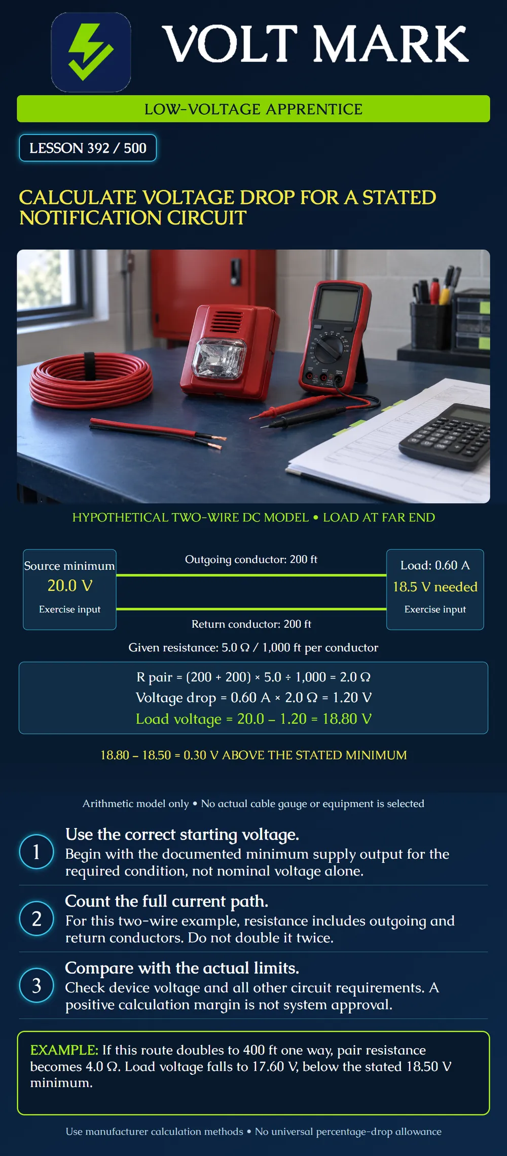
Calculate wire resistance, voltage drop and remaining load voltage for a fully stated two-wire example. Distinguish passing one arithmetic comparison from approving an installed notification circuit.
System Sensor's Audible Visible Appliance Reference Guide, section 11, describes evaluating wiring loss using the minimum supply voltage, circuit current and wiring resistance. It presents a far-end lumped-load model and notes that detailed analysis can account for individual appliance locations. This lesson uses original numbers, not the guide's example.
The guide is historical. Its assumed percentage below nominal is not a universal source-voltage rule, and unrelated older mounting/code tables are not used here. Obtain the correct values and calculation method for the actual equipment.
Use a simplified two-wire DC circuit with all modeled notification load at the far end: Minimum source voltage under the stated condition: 20.0 V. One-way cable route length: 200 ft. Resistance of each conductor: 5.0 ohms per 1,000 ft. Total modeled alarm load current: 0.60 A. Required minimum voltage at the modeled load: 18.50 V.
These are assigned exercise values, not ratings of a selected panel, cable gauge or appliance. The resistance value is assumed valid for the modeled condition. Added contact and module losses are assumed zero only for this simplified exercise. Real losses and temperature effects must be included where required.
The outgoing conductor runs 200 ft to the load. The return conductor runs 200 ft back. Total conductor length is 400 ft.
The word “return” here means the second conductor of the electrical current path. It does not declare a Class A redundant pathway. The drawing is a calculation model, not a termination or supervision diagram.
If supplied resistance already represents a pair or a completed circuit loop, do not multiply by two again. Write the resistance basis next to the number before doing any arithmetic.
R pair = total conductor length x resistance per unit length. R pair = 400 ft x 5.0 ohms / 1,000 ft = 2.0 ohms.
Equivalent calculation: R pair = 2 x 200 x 5.0 / 1,000 = 2.0 ohms.
Feet cancel, leaving ohms. Using only 200 ft would incorrectly give 1.0 ohm and underestimate the loss in this two-conductor model.
V drop = current x resistance. V drop = 0.60 A x 2.0 ohms = 1.20 V.
The example assigns a fixed design current. Actual electronic notification appliances may not behave as simple fixed resistors. Use the current basis and calculation method required by their documentation, including the applicable settings and supply waveform.
V load = minimum source voltage - wiring drop. V load = 20.0 - 1.20 = 18.80 V.
Compare with the stated 18.50 V minimum: 18.80 - 18.50 = 0.30 V.
The result is 0.30 V above that input threshold. It passes this one stated voltage comparison under the exercise assumptions. It does not establish equipment compatibility, synchronization, output capacity, maximum permitted voltage, battery performance or complete installation compliance. Additional project requirements could also require more allowance.
Do not replace the device-specific comparison with an invented universal percentage. A percentage can describe a result mathematically, but it does not by itself establish the permitted drop for the actual equipment.
Double the one-way route to 400 ft while retaining all other assigned inputs: Total conductor length = 800 ft. Pair resistance = 800 x 5.0 / 1,000 = 4.0 ohms. Voltage drop = 0.60 x 4.0 = 2.40 V. Load voltage = 20.0 - 2.40 = 17.60 V. Shortfall = 18.50 - 17.60 = 0.90 V.
The revised scenario fails the stated minimum-voltage comparison. Do not solve the conflict by changing appliance settings or equipment in the field without the responsible design process.
Return to a 200 ft route and split the same total modeled current into two loads: 0.30 A at 100 ft and 0.30 A at 200 ft. Assume each load retains the stated current, the same conductor resistance applies and no other losses occur.
The first 100 ft segment has two-conductor resistance: 2 x 100 x 5.0 / 1,000 = 1.0 ohm. It carries both loads, 0.60 A, so its drop is 0.60 V. Voltage at the first load is 20.0 - 0.60 = 19.40 V.
The second 100 ft segment also has pair resistance 1.0 ohm. It carries only the downstream 0.30 A, so it loses another 0.30 V. Voltage at the final load is 19.40 - 0.30 = 19.10 V.
The far-end lumped model gave 18.80 V because it carried the full 0.60 A over the entire modeled route. The distributed example gives 19.10 V under its different, explicitly stated load locations. Do not use this comparison to bypass the equipment manufacturer's required calculation method.
Retain the source-voltage basis, current data/settings, cable resistance basis, route lengths, topology, calculation method, device limits and drawing revision. Identify assumptions and unresolved losses. Keep the arithmetic with the inputs so another person can reproduce it.
Consulted October 1, 2026; opened: System Sensor Audible Visible Appliance Reference Guide, section 11, printed page 7: https://prod-edam.honeywell.com/content/dam/honeywell-edam/hbt/en-us/documents/manuals-and-guides/reference-guides/hbt-fire-AV_Appliance_AppGuide_AVAG266.pdf
All exercise numbers and diagrams are original. Historical sample limits are not generalized.
Mistake: Using one-way route length with a per-conductor resistance value. Correction: Include outgoing and return conductors; do not double again if the supplied value already describes the pair.
Mistake: Using nominal supply voltage when the model requires minimum source voltage. Correction: Record and use the applicable worst-case source basis before subtracting the calculated loss.
Mistake: Using the full circuit current in every segment of the distributed example. Correction: For each segment, total only its downstream loads and accumulate the segment drops to the endpoint.
Texas journeyman, 15 questions, scored by topic against the 70% mark. No card, and no account needed to start.
Free study material for low-voltage apprentices. This is a national foundation course: requirements differ by state and by local jurisdiction, and a practice that is common in one place is not a rule everywhere. Nothing here is a licence, a certification, or authority to work unsupervised, and completing it does not count as apprenticeship hours or continuing-education credit. Check the codes adopted where you are working, the licensing authority for that work, and your employer's safety programme. VoltMark is not affiliated with, endorsed by, or sponsored by NFPA, OSHA, NICET, BICSI, FOA, or any state or local licensing authority.

Electrician licensing exam prep: practice questions, timed exam simulations, and step-by-step help finding every answer in the NEC.