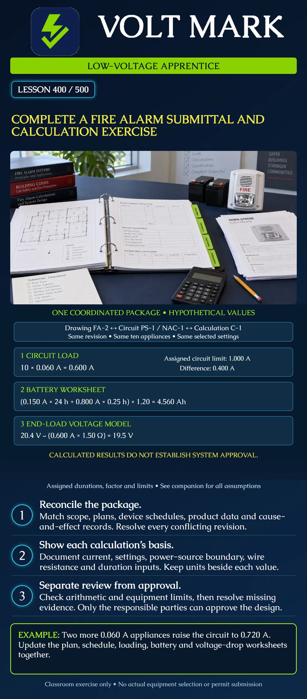
Assemble a coordinated classroom fire-alarm submittal record and solve circuit-loading, battery and voltage-drop calculations from explicit assigned inputs. Identify what the arithmetic proves and what still needs product evidence, qualified design review and jurisdictional approval.
A submittal communicates the proposed work and its supporting evidence. Wisconsin DSPS's published fire-alarm guidance, for example, requests plans, applicable material data, battery and voltage-drop calculations, and a project-specific sequence narrative or matrix. This illustrates the relationship between documents. Its submission procedures and jurisdictional scope are not nationwide rules.
For a real project, identify the reviewing authority, applicable editions and amendments, scope, required professional responsibility, equipment instructions and current submission checklist. Do not transfer another jurisdiction's exemptions, forms or thresholds into the package.
The Fire-Lite ES-200X manual, LS10131-000FL-E:F, May 23, 2022, section 9, provides current and battery worksheets and a product-specific capacity-factor method. System Sensor's AV Appliance Applications Guide discusses voltage-drop considerations and Ohm's law. These sources support the methods, not the invented equipment values below. This exercise does not model an actual ES-200X configuration or prescribe universal standby/alarm durations.
Drawing FA-2, calculation sheet C-1 and the device schedule all identify PS-1 / NAC-1 with ten hypothetical appliances. Each draws 0.060 A in alarm at the assigned setting. The assigned circuit capacity is 1.000 A. Assume these values are suitable worst-case inputs for the classroom model; actual work requires the applicable listed data and compatibility evidence.
For the same hypothetical source, total battery-powered standby current is 0.150 A. Alarm current includes 0.200 A of internal and other assigned loads plus the 0.600 A appliance load, giving 0.800 A total. No load is counted twice. Standby is assigned as 24 hours, alarm as 15 minutes, and the exercise adds 20 percent by multiplying by 1.20. These are exercise assumptions, not universal requirements.
For voltage drop, assign 20.4 V available at the circuit source under the modeled condition, 150 ft one-way distance, and 5.00 ohms per 1,000 ft for each conductor. Use a two-conductor DC end-load model that places the entire appliance current at the far end. Assign 18.5 V as the minimum load voltage. The model has no additional connector or interface loss. All such values need support in a real design.
10 × 0.060 A = 0.600 A. 1.000 A − 0.600 A = 0.400 A arithmetic difference.
The result is below the assigned individual-circuit limit. It does not establish total-source capacity, compatibility, synchronization, coverage or permission to add any particular equipment. Check aggregate and individual limits separately using actual product rules.
15 minutes ÷ 60 = 0.25 hour. Standby requirement: 0.150 A × 24 h = 3.600 Ah. Alarm requirement: 0.800 A × 0.25 h = 0.200 Ah. Subtotal: 3.600 + 0.200 = 3.800 Ah. Assigned factor: 3.800 × 1.20 = 4.560 Ah.
This is a calculated capacity requirement under the stated assumptions, not a battery selection. Approved battery type, voltage, charging capacity, enclosure fit, environmental criteria and required aging allowances remain to be checked. Do not round down to force a preferred battery to fit. A 20-percent addition is not the same calculation as assuming only 80 percent of nominal capacity is usable.
Total conductor length: 2 × 150 ft = 300 ft. Pair resistance: 300/1,000 × 5.00 ohms = 1.50 ohms. Drop: 0.600 A × 1.50 ohms = 0.900 V. Far-end voltage: 20.4 − 0.900 = 19.5 V. Difference above assigned minimum: 19.5 − 18.5 = 1.0 V.
The return conductor is included; this is not a statement that the circuit has a Class A return pathway. A distributed-load method considers each segment's current and resistance. The chosen method must suit the actual system and approval basis. Include applicable component losses, temperature effects and required source conditions when supported by the real design.
Prepare a classroom index containing scope and design basis; plans and circuit/riser references; equipment and device schedules; product and compatibility evidence; power, battery and voltage calculations; and cause-and-effect/interface records. For each item identify a document number, revision, responsible reviewer and open issues.
Check that the ten appliances appear consistently on FA-2, the schedule and C-1. Confirm the selected settings match the current data used. Keep source PS-1 and circuit NAC-1 identifiers consistent. Record why the chosen wire resistance and source voltage apply. A correct formula with unsupported inputs is still an unresolved calculation.
Now add two identical appliances. Keep every other classroom assumption unchanged, including the end-load distance and assigned zero standby contribution from these added appliances.
Revised circuit current: 12 × 0.060 = 0.720 A. Circuit difference: 1.000 − 0.720 = 0.280 A. Revised total alarm current: 0.200 + 0.720 = 0.920 A. Revised capacity: (0.150 × 24 + 0.920 × 0.25) × 1.20 = (3.600 + 0.230) × 1.20 = 4.596 Ah. Revised drop: 0.720 × 1.50 = 1.080 V. Revised load voltage: 20.4 − 1.080 = 19.320 V.
Update all affected records. If the actual route changes, recalculate its resistance too. An unchanged drawing with a revised twelve-device worksheet is inconsistent.
The classroom arithmetic is internally consistent. Actual manufacturer values, compatibility evidence, full source capacity, required durations, approved battery selection, coverage and interface requirements are not supplied. Mark those as pending real-project evidence. Do not label this exercise “approved for construction” or submit it as a real permit package.
Q1. Why is battery alarm current 0.800 A while NAC current is 0.600 A?
Q2. Why double the one-way distance?
Q3. Is 4.560 Ah a selected battery?
Q4. What changes after adding two appliances?
Q5. Does meeting the three arithmetic comparisons approve the system?
Wisconsin DSPS, Fire Alarm Plan Submittal Guidelines: https://dsps.wi.gov/a-z-programs-list/fire-suppression-and-fire-alarm-systems/references/fire-alarm-plan-submittal-guidelines/ Fire-Lite ES-200X Series Manual, LS10131-000FL-E:F, section 9: https://prod-edam.honeywell.com/content/dam/honeywell-edam/hbt/en-us/documents/manuals-and-guides/installation-guides/ba-fire-ES-200X-Manual-LS10131-000FL-E-F.pdf System Sensor AV Appliance Applications Guide, voltage-drop material: https://prod-edam.honeywell.com/content/dam/honeywell-edam/hbt/en-us/documents/manuals-and-guides/reference-guides/hbt-fire-AV_Appliance_AppGuide_AVAG266.pdf
These sources were opened. Austin's checklist appeared in search but returned404 when opened; it was not relied on for the lesson. All quantities, equipment limits, identifiers and project assumptions here are original classroom assignments.
Mistake: Using NAC current as the entire source alarm current. Correction: Keep the source's other 0.200 A load in the battery calculation while using only the assigned circuit current for its wiring loss.
Mistake: Updating the calculation to twelve devices while leaving the drawing at ten. Correction: Revise the linked drawing, schedule and calculation records together under document control.
Mistake: Calling the calculated amp-hour requirement a battery selection. Correction: Retain the required type, voltage, charging and enclosure checks before selecting equipment.
Independently recalculate the assigned project with eleven appliances. Retain 0.060 A per appliance, 0.200 A of other alarm loads, 0.150 A standby, 24 hours standby, 15 minutes alarm, the 1.20 factor and 1.50 ohms pair resistance. State the circuit current, total alarm current, adjusted capacity and far-end voltage.
Answer guide: circuit current is 0.660 A; total alarm current is 0.860 A. Capacity is (3.600 + 0.860 x 0.25) x 1.20 = 4.578 Ah. Drop is 0.660 x 1.50 = 0.990 V, leaving 19.410 V. Update every document carrying the quantity or affected result; these figures remain conditional classroom comparisons.
Texas journeyman, 15 questions, scored by topic against the 70% mark. No card, and no account needed to start.
Free study material for low-voltage apprentices. This is a national foundation course: requirements differ by state and by local jurisdiction, and a practice that is common in one place is not a rule everywhere. Nothing here is a licence, a certification, or authority to work unsupervised, and completing it does not count as apprenticeship hours or continuing-education credit. Check the codes adopted where you are working, the licensing authority for that work, and your employer's safety programme. VoltMark is not affiliated with, endorsed by, or sponsored by NFPA, OSHA, NICET, BICSI, FOA, or any state or local licensing authority.

Electrician licensing exam prep: practice questions, timed exam simulations, and step-by-step help finding every answer in the NEC.