Review copper and fiber segments as separate, documented links. Calculate an original campus fiber allowance. Distinguish cable-plant acceptance from equipment power margin and identify what must be checked before turn-up.
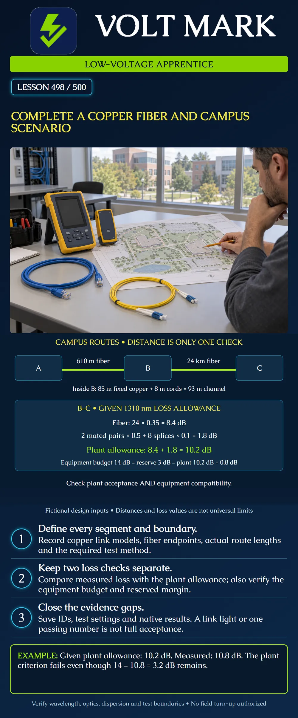
Buildings A and B are connected by a supplied installed fiber length of 610 m, approximately 2,000 ft. B and remote C are connected by 24 km of installed singlemode fiber, approximately 14.9 miles. These are fictional route lengths, including the cable included in the specified test boundary; do not substitute straight-line map distance.
Inside B, an ordinary balanced-copper LAN channel has 85 m of fixed cabling and 8 m total equipment/patch cords. The proposed service, components and test configuration must match the project requirements. This lesson does not claim every copper technology has a 100 m maximum.
No digging, aerial work, splice work or live optical testing is authorized by this exercise. Route access, utility coordination, environmental protection, entry details, cable ratings and any metallic-component requirements remain project-specific work items.
For this fictional standard LAN model, check the fixed portion and complete channel separately. The total is 85 + 8 = 93 m. Length alone is not a certification result.
Verify the selected test limit, category/class, adapter arrangement, cable IDs and native results. Confirm any power-delivery requirements separately, including the device and supply ratings, applicable cabling limits and installed conditions. Do not treat a continuity indication as proof of transmission performance.
A channel test and a permanent-link test represent different boundaries. Do not relabel a result from one model as the other. The approved project specification determines the required acceptance package.
The following values are GIVEN only for this arithmetic exercise. They are not universal component limits, a standard's default values or a product recommendation:
The designer has already defined which end connections and cords are included. Real test references must correspond to that boundary. Adding uncounted patching or changing the test reference invalidates a casual comparison.
Fiber: 24 km × 0.35 dB/km = 8.4 dB. Mated connections: 2 × 0.50 dB = 1.0 dB. Splices: 8 × 0.10 dB = 0.8 dB. Total: 8.4 + 1.0 + 0.8 = 10.2 dB.
Count mated pairs, not each plug as an independent connection. Maintain the actual splice and patch record instead of guessing counts from a route sketch.
Given equipment budget minus reserve minus plant allowance: 14 − 3 − 10.2 = 0.8 dB remaining beyond the required reserve.
That positive result supports only the stated budget comparison. It is not a full system design approval. Confirm wavelength, fiber and connector compatibility, service rate, dispersion limits, actual transmitter/receiver specifications, receiver overload limits and the manufacturer's application conditions. Evaluate both directions where the system requires them.
A short link can also need a receiver-overload check. A long link with acceptable attenuation can still be unsuitable for a service because of other limits. “Singlemode” and a distance label alone do not guarantee operation.
The supplied training result for B–C is 10.8 dB at the evaluated wavelength. Assume for this exercise that the correct test boundary and reference were used and the measurement has been validated under the project's decision rule.
Compare with plant allowance: 10.8 − 10.2 = 0.6 dB over the limit. Compare with equipment budget: 14 − 10.8 = 3.2 dB remaining, which is 0.2 dB beyond the fictional 3 dB reserve.
The cable-plant criterion still fails. Do not accept a deficient plant simply because the electronics may tolerate it. Escalate the discrepancy, retain the original result and investigate under the approved process.
In real acceptance, measurement uncertainty and the specified decision rule matter. Do not round a marginal value into a pass or invent a tolerance not in the agreed procedure.
Record the exact route and fiber IDs, endpoints, length basis, connector/splice inventory, wavelength, reference method, instrument details and required direction information. Keep raw/native test files and an intelligible summary tied to the as-built record.
Use insertion-loss results for the specified end-to-end acceptance. Where required, event-location testing helps investigate component events; a trace is not automatically a substitute for the specified loss measurement. Preserve the initial failed record and identify any later retest.
A–B needs its own calculation and results. B–C's budget cannot be copied onto the 610 m link because lengths, patching, service and equipment may differ. Campus acceptance is a set of verified segments and interfaces, not one campus-wide PASS label.
FOA, power and loss budgets: https://www.thefoa.org/tech/lossbudg.htm Supports the distinction between plant loss and equipment budget, component accounting and compatible measurement boundaries. All numerical inputs above are original fictional assumptions. FOA, insertion-loss cable testing: https://www.thefoa.org/tech/ref/testing/test/OFSTP-14.html Supports identifying the test boundary and reference method. Fluke Networks, Top 10 Cable Testing Mistakes: https://www.flukenetworks.com/blog/cabling-chronicles/top-10-cable-testing-mistakes Supports the ordinary LAN permanent-link/channel distinction. No universal claim for every copper system is made. Access note: an attempted FOA OLTS.html page failed; no claim relies on it.
Combine the two B-C decisions without merging their criteria. The validated 10.8 dB measurement is 10.8 - 10.2 = 0.6 dB above the supplied plant allowance, so record a plant discrepancy. Separately, 14 - 10.8 = 3.2 dB remains within the equipment budget; subtracting the 3 dB reserve leaves 0.2 dB. The second result does not reverse the first. Retain the failed plant record and request the approved investigation and retest. The copper channel's 85 + 8 = 93 m total is another separate check, and the A-B fiber segment still needs its own criteria and evidence.
Mistake: Marking the campus accepted because B-C still has 3.2 dB of equipment headroom. Correction: Evaluate the 10.8 dB result against the 10.2 dB plant allowance separately. It exceeds that allowance by 0.6 dB despite the remaining equipment reserve; preserve and resolve the discrepancy.
Mistake: Counting each connector plug as a separate 0.50 dB mated connection in this example. Correction: Count the two supplied mated pairs once each, giving 1.0 dB. Match the actual patching inventory and agreed measurement boundary before applying any allowance.
Mistake: Calling the 93 m copper channel a certified permanent link or copying B-C's pass criteria to A-B. Correction: Keep each segment and test boundary distinct. Length arithmetic does not replace the correct copper certification result, and A-B needs its own documented fiber calculation and tests.
Texas journeyman, 15 questions, scored by topic against the 70% mark. No card, and no account needed to start.
Free study material for low-voltage apprentices. This is a national foundation course: requirements differ by state and by local jurisdiction, and a practice that is common in one place is not a rule everywhere. Nothing here is a licence, a certification, or authority to work unsupervised, and completing it does not count as apprenticeship hours or continuing-education credit. Check the codes adopted where you are working, the licensing authority for that work, and your employer's safety programme. VoltMark is not affiliated with, endorsed by, or sponsored by NFPA, OSHA, NICET, BICSI, FOA, or any state or local licensing authority.

Electrician licensing exam prep: practice questions, timed exam simulations, and step-by-step help finding every answer in the NEC.