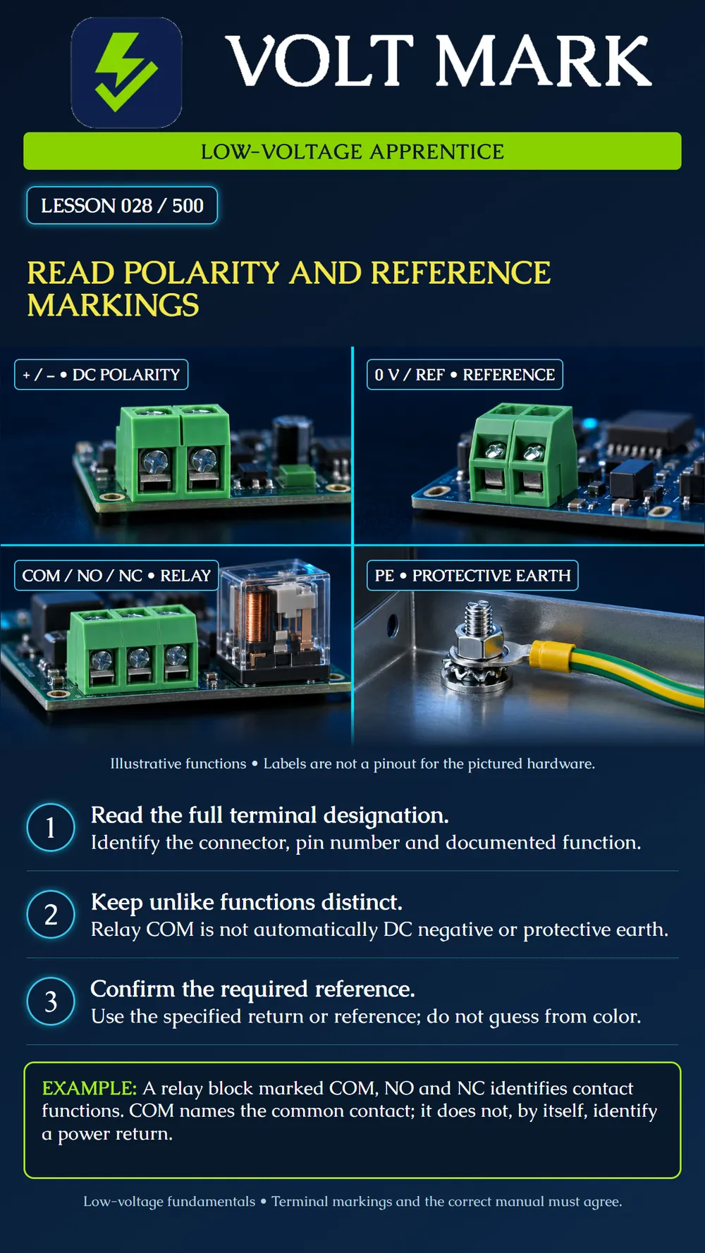
Read terminal markings in context and distinguish DC polarity, a circuit reference, relay contact common and a protective-earth connection.
DC polarity: plus and minus indicate polarity of the documented DC connection. Confirm whether the connector is an input, output or another circuit before interpreting it. Circuit reference: 0 V, REF or a manufacturer's GND label may designate a circuit reference or return. The exact meaning comes from that equipment's documentation. Relay contacts: COM, NO and NC identify the common, normally open and normally closed contacts in the documented normal state. Protective earth: PE identifies a protective-earth function. Do not substitute it for a required signal reference or ordinary power-return terminal.
A fictional trainer manual lists: J1 pin 1: DC input positive. J1 pin 2: DC input return. J2 pin 1: relay COM. J2 pin 2: relay NO. J2 pin 3: relay NC. A chassis point is separately identified as PE. On paper, label J1 as the power input and J2 as the relay-contact connector. Mark PE as a separate function. Do not draw a jumper from J2 COM to J1 return just because the word “common” sounds like a shared negative.
As a real manufacturer example, the Axis A9210 documentation identifies DC ground as a 0 V reference and separately identifies relay COM. It also describes a jumper that can feed DC power to relay COM. This demonstrates why COM alone cannot establish a terminal's voltage or function in a particular configuration. It is not an instruction to fit that jumper on another product.
A fictional worksheet states that point A is +12 V relative to point B. That statement compares two points. Reversing the mathematical reference gives point B as −12 V relative to point A. A minus sign in a DC reading describes that polarity relationship; it is not enough by itself to diagnose a fault. Before interpreting any actual reading, confirm the named reference points and the instrument configuration. Do not treat a chassis point as the reference merely because it is convenient.
Q: Is a red conductor sufficient proof of positive polarity? A: No; confirm documented identification and the actual circuit. Q: Is relay COM automatically power negative? A: No. Q: Does a terminal marked GND always mean protective earth? A: No; the manufacturer may use it for circuit reference. Q: Does the physical order COM–NO–NC apply to every relay? A: No; use the particular pinout. Q: Can the lesson's four picture labels be used as a wiring diagram? A: No; they distinguish functions only.
Joining terminals because their names sound similar, without checking the connector's purpose and configuration.
Read the complete terminal label, connector name and pinout. Power negative, circuit reference, relay common and protective earth are different functions. Some systems connect certain references by design, but you must confirm that design rather than assume it.
Axis, AXIS A9210 Network I/O Relay Module, connector and relay-power-jumper documentation: https://help.axis.com/en-us/axis-a9210 The J1/J2 trainer and point-A/point-B exercise are original fictional teaching examples.
Free study material for low-voltage apprentices. This is a national foundation course: requirements differ by state and by local jurisdiction, and a practice that is common in one place is not a rule everywhere. Nothing here is a licence, a certification, or authority to work unsupervised, and completing it does not count as apprenticeship hours or continuing-education credit. Check the codes adopted where you are working, the licensing authority for that work, and your employer's safety programme. VoltMark is not affiliated with, endorsed by, or sponsored by NFPA, OSHA, NICET, BICSI, FOA, or any state or local licensing authority.

Electrician licensing exam prep: practice questions, timed exam simulations, and step-by-step help finding every answer in the NEC.