Use actual conductor length and applicable resistance-per-length data to predict wire-loop resistance in a simple paired DC circuit.
Resistance increases with length. For the same material and temperature, a larger conducting cross-sectional area reduces resistance. Insulation thickness and overall cable diameter do not by themselves establish conductor area. In AWG sizes, a smaller gauge number generally denotes a larger conductor. Confirm the cable's specification rather than choosing by appearance. Construction, material and temperature also matter.
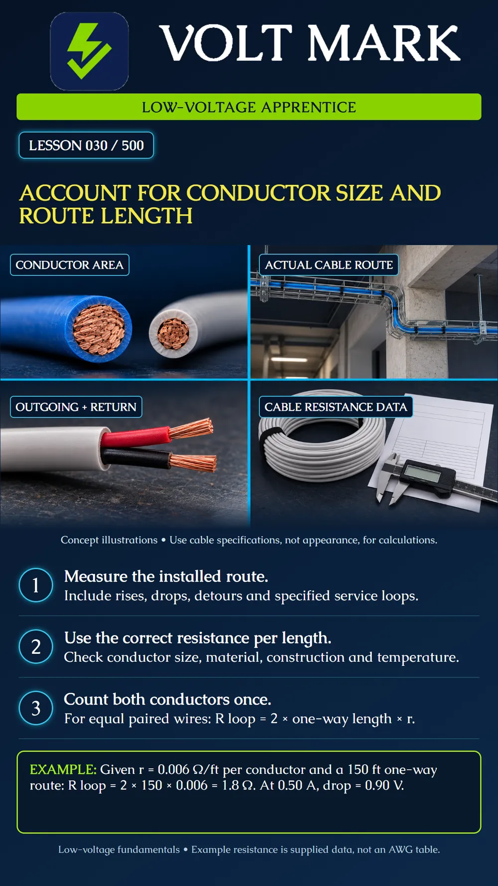
The copper cross sections illustrate area, without assigning an AWG size. The cable route illustrates detours rather than a straight line between endpoints. The two-core cable reminds you to include outgoing and return paths. The documentation represents the applicable manufacturer's conductor resistance data. A caliper or visual comparison does not replace that data.
A fictional installation sketch specifies this one-way route: Horizontal run: 110 ft. Rises and drops: 20 ft total. Detour around an obstruction: 10 ft additional. Specified service-loop allowance: 10 ft total. Actual one-way conductor route: 150 ft. For two equal conductors following that same route, the combined conductor length is 300 ft. This is 150 ft of two-core cable containing 300 conductor-feet; it is not a direction to order 300 ft of that cable.
The exercise supplies a hypothetical resistance of 0.006 Ω/ft for each conductor under the stated conditions. It is not presented as a universal value for any AWG size. R wire loop = 2 × 150 ft × 0.006 Ω/ft = 1.8 Ω. At the specified 0.50 A: V drop = 0.50 A × 1.8 Ω = 0.90 V. Using only the 110 ft horizontal run would produce 1.32 Ω and 0.66 V drop, understating the actual route's loss.
Option A uses the original hypothetical conductor data: 0.006 Ω/ft. Option B has verified worksheet data of 0.004 Ω/ft at the same conditions. With the same 150 ft one-way route: A: R loop = 1.8 Ω; drop at 0.50 A = 0.90 V. B: R loop = 1.2 Ω; drop at 0.50 A = 0.60 V. This comparison identifies a lower-resistance option. It does not establish that Option B meets every terminal, cable-listing or system requirement.
If the applicable data instead reads 6 Ω per 1,000 ft per conductor: 6 ÷ 1,000 = 0.006 Ω/ft. Use the units consistently. A value already expressed as loop resistance for a cable pair must not be doubled again. If outgoing and return conductors differ, calculate each resistance separately and add them rather than applying the equal-wire shortcut.
Answer: R loop = 3.6 Ω and drop = 1.80 V at 0.50 A.
Answer: No; conductor material and conducting area must be identified.
Answer: No; installed conductor length contributes resistance.
Answer: No; account for the actual approved route.
Answer: No.
Check equipment terminal capacity, wiring method, environmental suitability, listing and all applicable system requirements separately. Data transmission limits are also separate from a simple DC voltage-drop result. The worksheet assumes one load and two equal conductors carrying the same current. Distributed loads, shared returns or parallel conductor arrangements require the actual circuit model. Do not replace required route planning with an arbitrary extra percentage. Record the measured or specified route allowances clearly.
Confusing cable-feet, conductor-feet and the one-way length requested by a calculator.
Use the actual route, the actual conductor data and consistent units. In our example, 150 feet one way means 300 conductor-feet in the paired circuit. At 0.006 ohm per foot, the wire loop is 1.8 ohms and loses 0.9 volt at half an amp.
Belden, DC Powering Max Reach Calculator: https://tools.belden.com/dc-max-reach-calculator/ OpenStax, Physics, series-circuit resistance principles: https://openstax.org/books/physics/pages/19-2-series-circuits All route lengths and resistance figures above are original hypothetical worksheet data, not specifications for a named cable.
Free study material for low-voltage apprentices. This is a national foundation course: requirements differ by state and by local jurisdiction, and a practice that is common in one place is not a rule everywhere. Nothing here is a licence, a certification, or authority to work unsupervised, and completing it does not count as apprenticeship hours or continuing-education credit. Check the codes adopted where you are working, the licensing authority for that work, and your employer's safety programme. VoltMark is not affiliated with, endorsed by, or sponsored by NFPA, OSHA, NICET, BICSI, FOA, or any state or local licensing authority.

Electrician licensing exam prep: practice questions, timed exam simulations, and step-by-step help finding every answer in the NEC.