Trace a changeover contact from COM to NC or NO in two defined relay states without renaming the terminals.
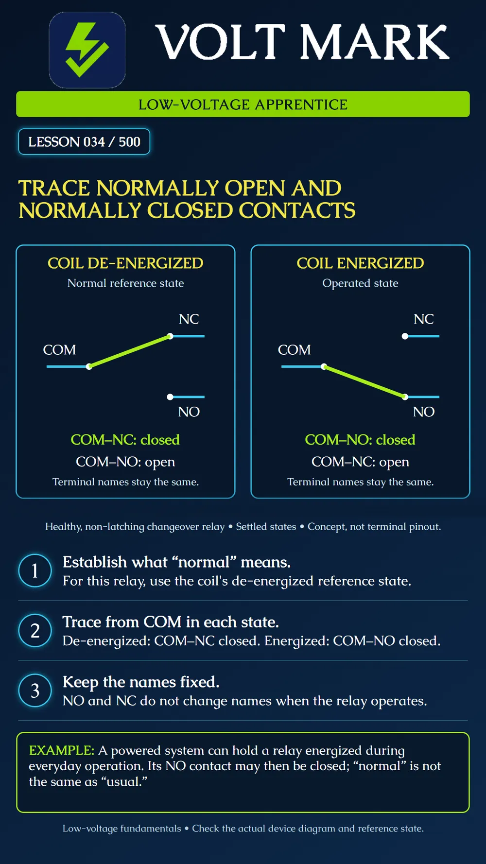
The poster uses a healthy non-latching, single-stable changeover relay. Its normal reference state is coil de-energized. In that state, COM connects to NC and is separated from NO. When the coil is properly energized and the relay has operated, COM connects to NO and is separated from NC. The diagram shows settled states, not the timing of transfer between them.
Start at COM on the left side of each contact set and follow the lime moving contact. Left drawing: its tip touches NC. There is a gap to NO. Right drawing: its tip touches NO. There is a gap to NC. The terminal labels remain in the same positions and keep their names. NO means normally open, not “open at this instant regardless of relay state.”
A fictional training relay K1 has a coil and one changeover contact. The instructor specifies the same healthy non-latching behavior as the poster. Fill in the table: Coil de-energized — COM to NC: closed; COM to NO: open. Coil energized and operated — COM to NC: open; COM to NO: closed. Coil returned to de-energized and settled — COM to NC: closed; COM to NO: open. These are expected states for the stated model, not proof of an actual relay's condition.
A worksheet shows an external low-voltage signal source connected to COM and a receiving input connected to NO. When K1 is de-energized, that contact path is open. When K1 operates, the contact path closes. Now move the drawn receiving-input connection from NO to NC. The expected contact states reverse. This is a paper tracing exercise. It does not establish a receiving input's voltage compatibility, supervision arrangement or safety function.
“NORMAL” IS NOT “EVERYDAY” A system may intentionally keep a relay energized during its usual operating condition. The contact named NO can therefore be closed most of the working day. Likewise, do not define a door-contact marking solely from whether the door is usually closed. Magnetic actuation, device definitions and the manufacturer's reference state must be identified. The terms describe a specified reference condition, not the state a person happens to call normal in conversation.
A latching relay can retain a contact state after coil drive is removed, so it does not follow this non-latching return assumption. A failed contact, incorrect coil drive or mechanical problem can also make actual behavior differ from the expected table. This diagram does not describe transfer timing, contact ratings, coil polarity or a real terminal numbering pattern. Those details come from the particular product documentation. Do not equate NO or NC alone with an entire door's fail-safe or fail-secure behavior; that depends on the complete system design.
Q: In the poster's de-energized state, which path is closed? A: COM to NC. Q: After proper energization and operation, which path is closed? A: COM to NO. Q: Does NO become renamed NC when it closes? A: No. Q: Does “closed contact” prove a voltage source is present? A: No; contact state and source availability are separate. Q: Does loss of coil drive always reset every relay type? A: No; latching types are a notable exception. Q: Is the contact drawing a universal pinout? A: No.
Treating NO and NC as live status labels instead of names tied to the specified reference state.
Find the reference state, then trace from common. In our non-latching relay, de-energized means common connects to normally closed. After energization, common connects to normally open. The terminal names stay fixed even though the contact position changes.
Omron, relay technology and contact forms: https://components.omron.com/sg-en/products/basic-knowledge/relays/technology Omron, latching-relay retention: https://components.omron.com/eu-en/faq/relays/FAQE10007 The K1 state table and signal-tracing exercises are original fictional teaching material.
Free study material for low-voltage apprentices. This is a national foundation course: requirements differ by state and by local jurisdiction, and a practice that is common in one place is not a rule everywhere. Nothing here is a licence, a certification, or authority to work unsupervised, and completing it does not count as apprenticeship hours or continuing-education credit. Check the codes adopted where you are working, the licensing authority for that work, and your employer's safety programme. VoltMark is not affiliated with, endorsed by, or sponsored by NFPA, OSHA, NICET, BICSI, FOA, or any state or local licensing authority.

Electrician licensing exam prep: practice questions, timed exam simulations, and step-by-step help finding every answer in the NEC.