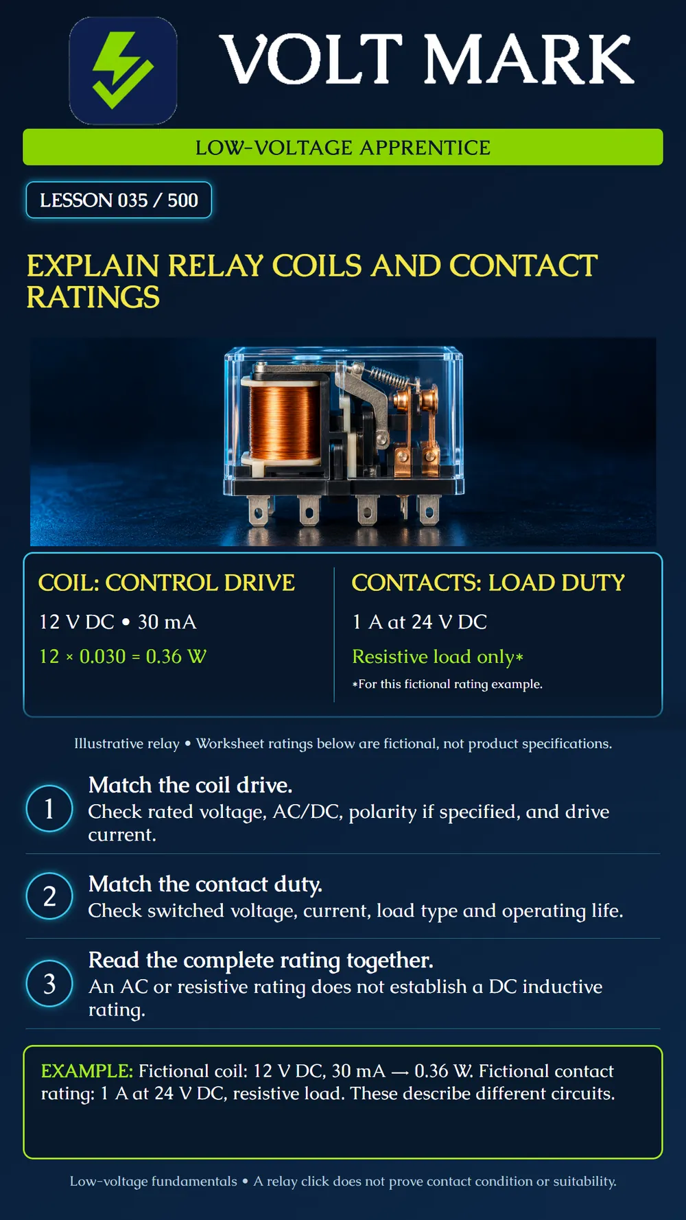
Separate relay coil requirements from contact ratings and interpret a stated switching rating in its full context.
The coil creates the magnetic action that operates an electromechanical relay. Its drive requirements belong to the control circuit. The contacts open, close or transfer another circuit. Their ratings describe the permitted switching or carrying duty under stated conditions. The coil's voltage and the switched circuit's voltage need not be equal. The contact rating is not the current the coil requires, and the coil label is not a specification for the load supply.
A training worksheet gives: Coil: 12 V DC, 30 mA at the stated nominal condition. Contact rating: 1 A at 24 V DC for a resistive load under the stated test conditions. Compute nominal coil input power: 30 mA = 0.030 A. P coil = 12 V × 0.030 A = 0.36 W. This 30 mA is not a 1 A contact load. The 1 A statement does not mean the coil needs 1 A, and it does not mean the relay supplies 24 V by itself.
Candidate load A is a fictional 24 V DC resistive load drawing 0.40 A. Its voltage, current and load category are within the worksheet's stated contact-rating pair. That is an initial check, not complete selection approval: operating life, environment and all other applicable limits remain to be checked. Candidate load B is a fictional 24 V DC solenoid drawing 0.40 A in its steady state. The given resistive-load rating alone does not establish suitability for this inductive load. Candidate drive C is a 24 V DC coil supply proposed for the specified 12 V coil. It does not match the stated nominal drive requirement. Do not confuse the 24 V contact figure with permission to apply 24 V to the coil.
For the coil, identify rated voltage, AC/DC type, required drive current or power, permitted operating range and any specified polarity. Pull-in and release conditions are separate characteristics, not interchangeable nominal ratings. For the contacts, identify the applicable voltage-current combination, AC/DC duty, resistive or inductive conditions, any inrush or minimum-load limits, and expected electrical life. Maximum switching voltage, maximum current and maximum switching power may be separate limits. Do not assume every maximum can be applied simultaneously. A carrying-current limit is also not automatically a make-or-break rating.
“Coil drive proposed: 12 V DC. Worksheet coil demand: 30 mA nominal. Proposed switched load: 24 V DC, 0.40 A solenoid. Only a resistive contact rating is supplied. Inductive suitability and suppression requirements remain unresolved.” This note identifies the missing evidence instead of selecting the relay from its largest printed number.
Q: Which part normally receives the control drive? A: The coil. Q: Which part switches the external load path? A: The contacts. Q: Does a 24 V contact rating specify a 24 V coil? A: No. Q: Does a relay click prove a healthy low-resistance contact path? A: No. Q: Can an AC contact rating automatically be used for an equal DC voltage and current? A: No; use the applicable manufacturer rating. Q: Is coil power in the example 0.36 W or 24 W? A: 0.36 W.
Treating all numbers on the relay as one interchangeable rating.
Read the coil and contacts separately. The coil needs the correct control drive; the contacts need the correct switching rating for the actual load. Our fictional twelve-volt, thirty-milliamp coil uses 0.36 watt. Its separate contact rating describes a different circuit and a stated resistive duty.
Omron, general-purpose relay precautions: https://www.ia.omron.com/product/cautions/36/safety_precautions.html Omron, G2R-S specification structure separating coil and contact ratings: https://www.ia.omron.com/products/family/1731/specification.html No numerical Omron product rating is asserted by the fictional examples above.
Free study material for low-voltage apprentices. This is a national foundation course: requirements differ by state and by local jurisdiction, and a practice that is common in one place is not a rule everywhere. Nothing here is a licence, a certification, or authority to work unsupervised, and completing it does not count as apprenticeship hours or continuing-education credit. Check the codes adopted where you are working, the licensing authority for that work, and your employer's safety programme. VoltMark is not affiliated with, endorsed by, or sponsored by NFPA, OSHA, NICET, BICSI, FOA, or any state or local licensing authority.

Electrician licensing exam prep: practice questions, timed exam simulations, and step-by-step help finding every answer in the NEC.