Recognize common coil loads, explain why switching can produce a transient and identify the information needed to select or verify the specified suppression.
A coil stores energy in a magnetic field. When its current is interrupted, the collapsing field can produce a voltage transient as current attempts to continue. That transient can stress switching contacts or electronics. Suppression provides a controlled way to limit the transient or dissipate stored energy. The appropriate method depends on the load, switching circuit and device requirements.
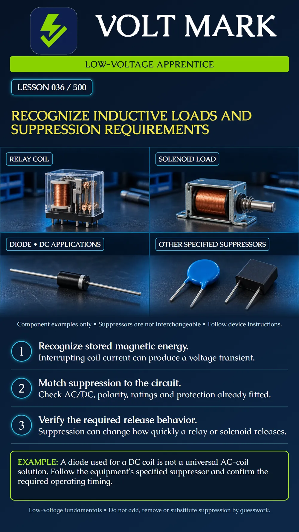
The relay and solenoid represent inductive loads commonly encountered in low-voltage controls. The diode is an example of a component used in some DC suppression arrangements. The varistor and RC module represent other possible manufacturer-specified approaches. Their appearance does not establish their ratings, suitability or internal construction. The loose parts are not an installation kit or a wiring diagram.
A plain flyback diode arrangement used across a DC coil is not a general solution for an AC coil. Its polarity and rating matter in the specified DC circuit. Some devices include suppression internally. AC applications can use other specified methods, such as appropriately rated RC networks or varistors. The actual manufacturer instructions govern the choice and installation. This recognition lesson does not prescribe component values or a universal connection diagram.
A suppression circuit can change how quickly coil current decays, altering relay or solenoid release time. A simple diode can delay release compared with some other suppression arrangements. For a device whose timing affects a required function, protection and release behavior must be evaluated together. Do not remove protection to make an actuator faster, or add a diode simply because one was used on another job.
A fictional low-voltage actuator kit includes a controller, an actuator and an approved suppression accessory. The worksheet presents three proposals:
Identify the load model and whether its coil is AC or DC. Identify the controller output type and its inductive-load limits. Check whether suppression is already inside the load or output module. Locate the specified accessory or circuit, including polarity when applicable. Identify the required placement and connection instructions. Record the required release behavior and the authorized functional test. Escalate missing or conflicting information before changing the arrangement.
“Actuator A is documented as a DC coil. The drawing specifies suppressor S1. S1's part identification is unreadable, so compatibility has not been established. No substitution has been made.” That report states the evidence and the unresolved item. “All coils need the same diode” would be an unsupported conclusion.
Q: What type of energy is stored by the energized coil? A: Magnetic-field energy. Q: Why does switching an inductive load require attention beyond its steady current? A: Interruption can produce a transient and switching stress. Q: Is a DC flyback diode automatically suitable across an AC coil? A: No. Q: Can suppression change release time? A: Yes. Q: Should internal suppression be checked before adding external parts? A: Yes. Q: Does a resistor-load contact rating establish the entire inductive application? A: No.
This lesson develops recognition and documentation skills. It does not authorize modification of access-control release behavior, fire-alarm interfaces or other required safety functions. Use the equipment-specific instructions and approved system design. Suppression does not replace correct contact ratings, protection, wiring or a suitable driver.
Selecting a suppressor by physical appearance or habit rather than the actual circuit and timing requirements.
Relay coils and solenoids store magnetic energy. Interrupting their current can create a transient. Use the suppression specified for the actual AC or DC circuit, check what is already built in, and confirm the required release behavior.
Omron, general-purpose relay precautions and surge-suppression examples: https://www.ia.omron.com/product/cautions/36/safety_precautions.html Omron, coil-relay surge countermeasures: https://components.omron.com/us-en/faq/relays/FAQE10041 The actuator kit, proposals and reporting example are original fictional teaching material.
Free study material for low-voltage apprentices. This is a national foundation course: requirements differ by state and by local jurisdiction, and a practice that is common in one place is not a rule everywhere. Nothing here is a licence, a certification, or authority to work unsupervised, and completing it does not count as apprenticeship hours or continuing-education credit. Check the codes adopted where you are working, the licensing authority for that work, and your employer's safety programme. VoltMark is not affiliated with, endorsed by, or sponsored by NFPA, OSHA, NICET, BICSI, FOA, or any state or local licensing authority.

Electrician licensing exam prep: practice questions, timed exam simulations, and step-by-step help finding every answer in the NEC.