Explain how cable type, support geometry, attachment and installation conditions determine support selection.
A support carries cable weight and helps maintain the cable's intended shape. The support, its fasteners and the structure receiving the load must all be suitable. A load rating on one component does not prove the assembled installation has that capacity.
Read the exact product instructions. Manufacturers offer support and attachment combinations for specific installation methods. Do not treat wall, ceiling and rod attachments as interchangeable merely because the cradle looks similar.
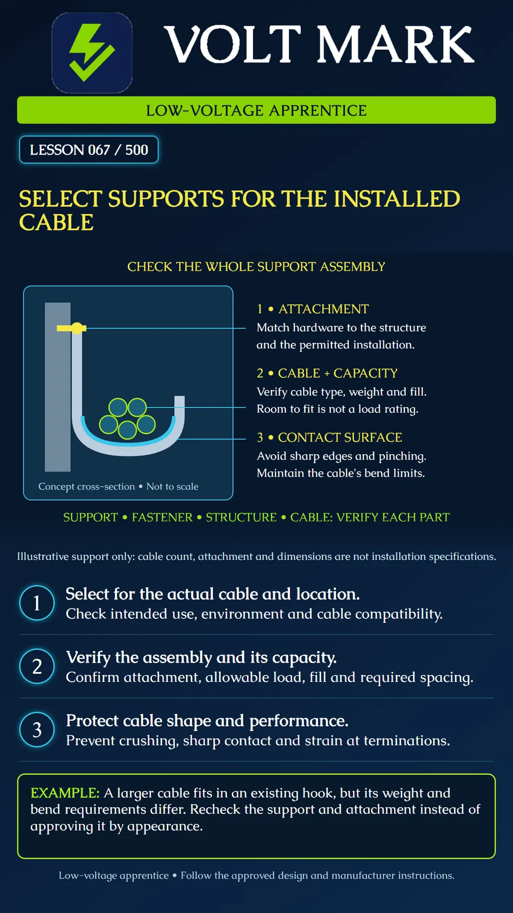
The poster shows a concept cross-section of a J-shaped support. Five circles represent cable cross-sections, not a permitted quantity. The cyan contact area emphasizes the surface carrying the cable. The yellow attachment is a symbol, not a specified anchor. Do not fabricate this drawing as a bracket or use its proportions for sizing.
Identify cable construction, outside diameter, installed weight and bend requirements. A support used for one communications cable arrangement may not suit a different fiber cable or heavier bundle. Verify permitted applications instead of assuming every low-voltage cable uses the same accessory.
FOA describes the need for supports that avoid distortion and stress in premises copper cabling. For fiber, crushing and tight restraint can affect optical performance or damage fibers. Appropriate restraint must not deform the jacket. A tidy bundle can still be damaged by over-tightened ties.
Physical room inside a hook is not allowable load. A published cable-count example may use a particular cable diameter. A different diameter or weight can change the selection. Verify the manufacturer's basis and approved design. Do not invent a universal maximum count.
Obtain required spacing from the governing installation requirements, approved design and product documentation. Consider supported length and weight, sag, direction changes and termination areas. This lesson gives no single spacing number for all support types.
Identify the actual structure and permitted fastening method. Check compatibility with the environment, including moisture or corrosion exposure where relevant. Resolve missing instructions before installation. An existing fastener is not proven adequate for additional load just because it has not visibly failed.
At direction changes, maintain the cable's required bend geometry. At vertical sections and equipment entries, address weight and strain relief with the specified method. A connector should not become the unintended support for a hanging run.
An existing hook carries small communications cables. A new project adds a heavier cable with different bend requirements. A trainee sees open space and proposes reusing every hook.
Record the new cable's identity, diameter, weight and limits. Identify the support model and attachment. Compare the combined installation with documented capacity, geometry and spacing requirements. If evidence is incomplete, obtain it or an approved revised arrangement before adding cable.
No to all four. Verify the actual cable, support, attachment and installation together.
Cable part number and relevant properties: Support and attachment part numbers: Structure and installation orientation: Capacity and fill basis: Spacing and bend provisions: Environment and restrictions: Document references and unresolved questions:
nVent CADDY — Cat HP J-Hook CAT21HPWH: product-specific support features, not universal ratings. https://www.nvent.com/en-ca/caddy/products/efscat21hpwh FOA — Installing UTP Cabling: avoiding stress and distortion. https://www.thefoa.org/tech/ref/premises/install.html FOA — Installing Fiber Optic Cable: restraint and vertical support considerations. https://www.thefoa.org/tech/ref/install/installcbl.html FOA — Premises Site Preparation: suitable support structures before installation. https://thefoa.org/tech/ref/install/premsite.html
No universal load, spacing or installation approval asserted. Original VoltMark logo and Caudex fonts retained.
Free study material for low-voltage apprentices. This is a national foundation course: requirements differ by state and by local jurisdiction, and a practice that is common in one place is not a rule everywhere. Nothing here is a licence, a certification, or authority to work unsupervised, and completing it does not count as apprenticeship hours or continuing-education credit. Check the codes adopted where you are working, the licensing authority for that work, and your employer's safety programme. VoltMark is not affiliated with, endorsed by, or sponsored by NFPA, OSHA, NICET, BICSI, FOA, or any state or local licensing authority.

Electrician licensing exam prep: practice questions, timed exam simulations, and step-by-step help finding every answer in the NEC.