Identify mounting, optical-path and verification constraints that affect an exterior photoelectric intrusion beam.
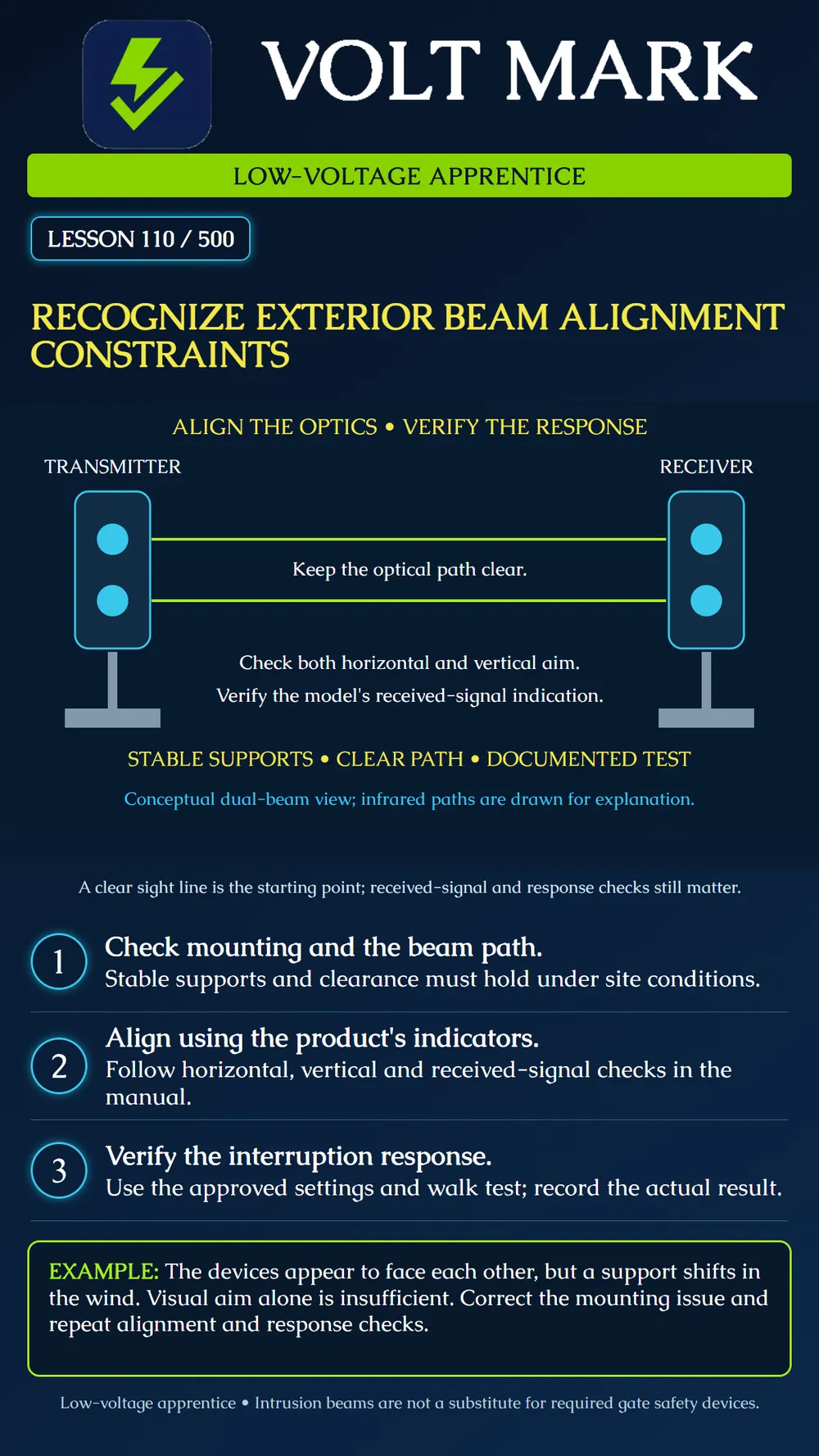
An active photoelectric beam system uses a transmitter and a receiver. Detection depends on the product's logic for interruption of the received beam or beams. The green lines on the poster illustrate otherwise invisible infrared paths; they are not a scale drawing. A pair that appears to face each other still needs the manufacturer's alignment and operational checks.
OPTEX's AX-TN/TF manual calls for solid mounting, avoidance of wind-moved obstructions and protection against direct sunlight entering the receiver. It provides horizontal and vertical alignment and received-level verification before the walk test. Other beam sources can interfere with an installation; channel features differ by model. Use the actual manual rather than assuming every product has frequency selection.
OPTEX's FAQ explains why weak alignment can worsen susceptibility to fog and sunlight and recommends the specified meter check where applicable. A universal test voltage cannot be assigned to every beam detector. Record the installed model, measurement method and its required criterion alongside the result.
Beam interruption timing is another constraint. OPTEX's technical guidance explains that increasing the interruption duration can reduce responses to brief disturbances but can also miss fast crossings if made excessive. Follow the approved setting and repeat the required test after adjustments. Timing changes are not a repair for a moving support or an obstructed path.
An installer records that a beam pair was visually aligned on a calm morning. Later, the instructor notices a loose support in the training setup. The correct conclusion is that the mounting needs attention, not that the receiver should simply be made less responsive. After the responsible person approves and completes the correction, alignment and response checks must be repeated. This is a fictional exercise, not evidence of a real system test.
Use an authorized outdoor training arrangement with the exact product instructions. Have the responsible person arrange any necessary monitoring test status and a safe walking route. This lesson does not authorize working in traffic, entering restricted property or testing a moving gate. Intrusion detection is a different function from machinery or gate entrapment protection.
Before adjusting anything, record the transmitter and receiver identifiers, model, intended path and mounting arrangement. Review the specified operating distance and any relevant placement restrictions. Do not substitute maximum optical arrival distance for the permitted detection distance.
Inspect the route with the instructor. Identify potential moving vegetation or other obstructions, the stability of each support and changes expected during normal site use. An observation during one calm period does not establish behavior in every season. Document concerns for the responsible designer or supervisor.
Follow the model's complete alignment procedure. Use only its designated indication or measurement points and the appropriate instrument. Record the expected criterion and observed value or indicator state. If the criterion is not met, retain the result as unresolved. Do not label it passed merely because the alarm indicator is currently off.
Perform the authorized operational test using the configured interruption setting and manufacturer procedure. Keep a received-level alignment check distinct from proof of the required alarm response. If panel or monitoring checks are part of the plan, document those stages separately. Restore the approved final configuration and system status through the responsible person's closeout process.
Transmitter / receiver identifiers and models: Manual revision / approved layout: Installed separation and permitted detection range: Supports / optical path / identified site constraints: Alignment instrument or indicator: Required criterion / actual result: Interruption setting and authorized test method: Observed detector response: Panel or monitoring evidence, if required: Open issue / owner / correction / retest: Final configuration and restoration confirmation:
Answer: No. Complete the product's received-level and response checks.
Answer: No. Correct the cause and retest.
Answer: No. Use equipment approved for the required safety function.
Researched 2026-09-30: OPTEX AX-TN/TF Installation Manual No.59-1282-6, precautions, alignment and walk test: https://s3-eu-west-1.amazonaws.com/optex-europe/sensor-downloads/Intrusion-Detection/Manuals/optex-ax-tn-tf-manual-en.pdf?mtime=20170307130142 OPTEX America FAQ, beam alignment: https://optexamerica.com/faq OPTEX Technical Information, adjustable beam interruption time: https://www.optex.co.jp/e/download-file/intrusion-detection/g1pdco00000025fn-att/g1pdco00000025g3.pdf Manufacturer examples are bounded to their products; no universal range, height, test voltage or legal requirement is claimed. Original diagram, scenario, practice and record form.
Free study material for low-voltage apprentices. This is a national foundation course: requirements differ by state and by local jurisdiction, and a practice that is common in one place is not a rule everywhere. Nothing here is a licence, a certification, or authority to work unsupervised, and completing it does not count as apprenticeship hours or continuing-education credit. Check the codes adopted where you are working, the licensing authority for that work, and your employer's safety programme. VoltMark is not affiliated with, endorsed by, or sponsored by NFPA, OSHA, NICET, BICSI, FOA, or any state or local licensing authority.

Electrician licensing exam prep: practice questions, timed exam simulations, and step-by-step help finding every answer in the NEC.