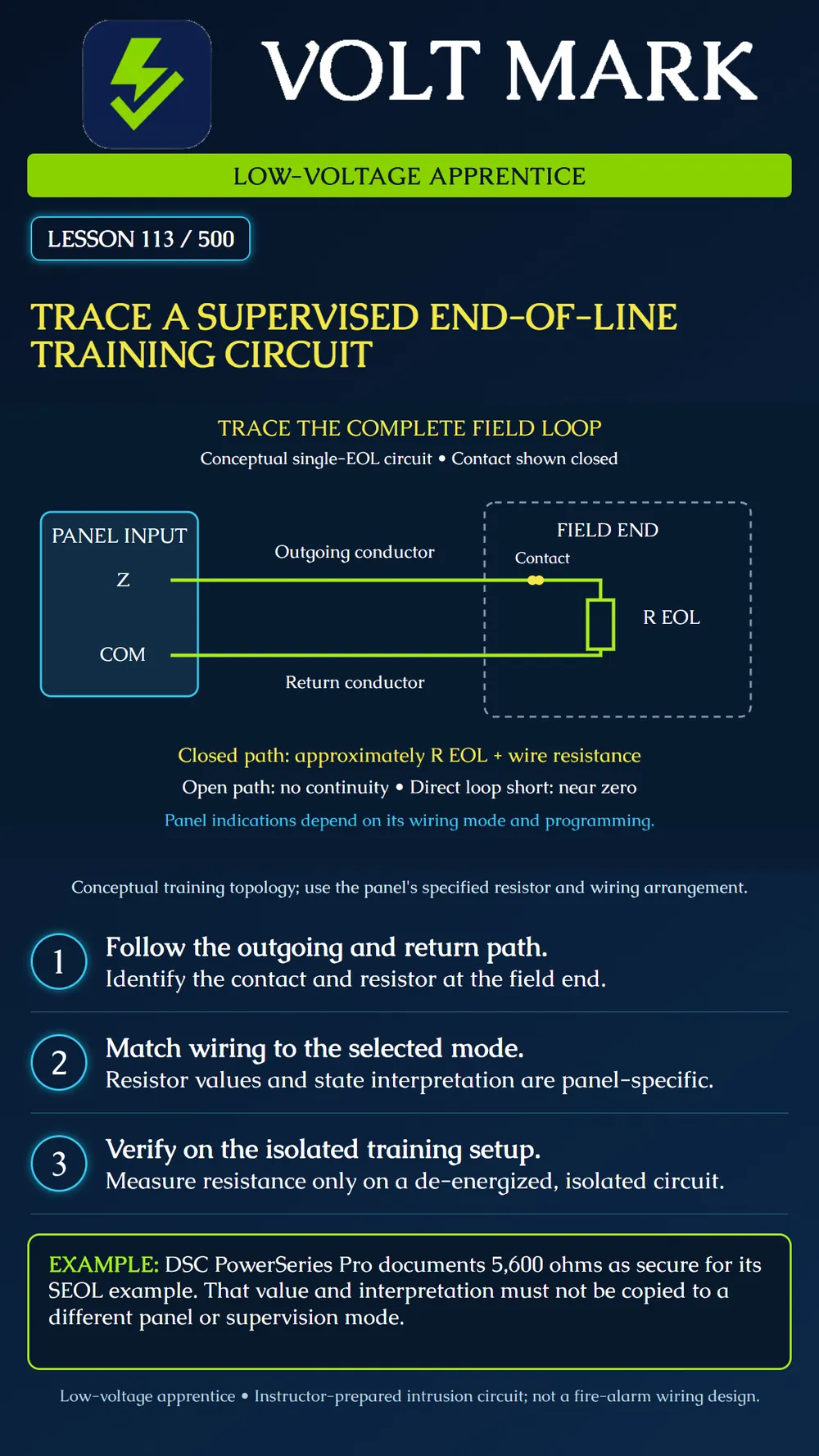
Trace a single end-of-line intrusion loop and distinguish its electrical path from the panel's interpretation.
Start at the zone input and follow the outgoing conductor to the field device. In this conceptual series arrangement, the contact is closed and the end-of-line resistor is at the field end. The return conductor completes the path to common. This is one arrangement, not a universal diagram for all detector types.
The closed loop presents approximately the EOL resistance plus conductor and connection resistance. Opening this series path removes continuity. A direct short between outgoing and return conductors before the field components presents a much lower resistance and bypasses those components electrically. These are descriptions of this circuit, not instructions to alter an installed security system.
DSC's PowerSeries Pro SEOL documentation specifies a field-end resistor and gives an example with 5,600 ohms representing secure, while an open or short represents alarm in its table. The example is tied to that wiring mode. A panel's actual annunciation, timing and reporting also depend on programming and system state. Do not infer a distinct tamper or trouble message from resistance alone.
An EOL resistor belongs at the location specified for the supervised field circuit. Placing it at the panel instead can leave the field wiring inadequately supervised. A resistor is not a guarantee that every possible wiring fault will be uniquely identified. More elaborate supervision arrangements use different component configurations and must be read separately.
Use an instructor-prepared intrusion training board, disconnected from production systems. Obtain the panel manual, intended wiring mode, required resistor and approved drawing. Have the instructor establish the permitted test conditions before handling conductors.
First trace the drawing with a pencil. Label both conductors, the contact and resistor. Then identify the corresponding parts on the training board without changing them. State which section is the field end and explain why its location matters.
For resistance checks, the instructor must establish that the loop is de-energized and isolated from the panel and other sources. Never use the meter's resistance function on a powered loop. Follow the meter instructions and the approved exercise. Record the expected resistance, actual reading and test points. Include instrument units.
If the instructor provides approved switches that simulate normal, open and short conditions, compare those states one at a time. Do not improvise shorts on a live panel. Keep an electrical observation separate from the panel's displayed condition. Where an energized panel demonstration is authorized, reconnect and operate it only through the instructor's procedure.
Record the configured supervision mode before comparing the panel response with its manual. A mismatch is an investigation item, not permission to move the resistor, change programming or bypass the zone to obtain a normal display. Restore the training arrangement after the demonstration and retain any unresolved discrepancy.
A student traces a series loop but stops at the contact and forgets the return conductor. The drawing is incomplete: an electrical loop needs a complete path back to the input circuit. The student traces both legs and identifies the resistor at the far end. On the isolated training board, the instructor then demonstrates how a break anywhere in that series path changes continuity. No real field test is claimed here.
Panel/model/manual revision: Supervision mode and resistor requirement: Drawing reference and field-end location: Contact state: Isolated test points: Expected resistance / measured resistance / units: Panel condition, if separately demonstrated: Discrepancy / instructor explanation / retest: Restoration confirmation:
Answer: No. Use the exact panel's instructions and selected mode.
Answer: Do not use resistance mode on an energized circuit.
Answer: No. Those circuits require their own approved design and instructions.
Researched 2026-09-30: DSC PowerSeries Pro Reference Manual, Single end-of-line resistor: https://docs.johnsoncontrols.com/dsc/r/DSC/en-US/PowerSeries-Pro-Reference-Manual/1.3.1/Installation/Installing-modules/Zone-wiring/Single-end-of-line-SEOL-resistor Manufacturer primary indexed material establishes the bounded example. Diagram, practice and record form are original instructional material.
Free study material for low-voltage apprentices. This is a national foundation course: requirements differ by state and by local jurisdiction, and a practice that is common in one place is not a rule everywhere. Nothing here is a licence, a certification, or authority to work unsupervised, and completing it does not count as apprenticeship hours or continuing-education credit. Check the codes adopted where you are working, the licensing authority for that work, and your employer's safety programme. VoltMark is not affiliated with, endorsed by, or sponsored by NFPA, OSHA, NICET, BICSI, FOA, or any state or local licensing authority.

Electrician licensing exam prep: practice questions, timed exam simulations, and step-by-step help finding every answer in the NEC.