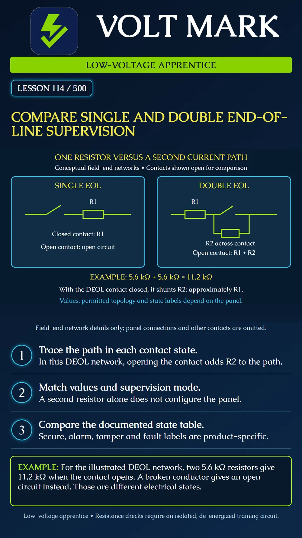
Compare two field-end networks and explain how a second resistor can distinguish a contact operation from a broken loop.
The poster enlarges only the field-end network; it omits the panel and return wiring. Both contacts are drawn open so the different available paths are visible. In the single-EOL example, R1 is in series with the contact. Closing the contact completes a path through R1. Opening it breaks that path.
In the double-EOL example, R1 remains in series with a parallel combination of the contact and R2. When the contact closes, its low-resistance path shunts R2, so the network is approximately R1. When the contact opens, the remaining path runs through R1 and R2 in series. Their resistances add. A broken conductor elsewhere in the loop still produces an open circuit.
Using two 5.6 kΩ resistors gives approximately 5.6 kΩ with the contact closed and 11.2 kΩ with it open, before accounting for wiring and component tolerances. This is not two resistors permanently connected in parallel. Trace the nodes rather than guessing from the component count.
DSC PowerSeries Pro's documented SEOL table calls 5,600 ohms secure and an open or short alarm. Its DEOL table identifies 5,600 ohms as secure, 11,200 ohms as alarm, an open loop as tamper and a short as fault. The DEOL instructions restrict this arrangement to normally closed devices and one normally closed contact per zone. These statements apply to the cited product and supervision mode; they are not universal panel behavior.
A wiring change does not automatically select the matching supervision mode. Device compatibility, resistor values, placement and programming must agree with the approved instructions. Actual annunciation and reporting also depend on the configured system. These diagrams are intrusion teaching examples, not fire-alarm designs.
Use an instructor-prepared training board disconnected from production systems. Obtain its approved drawing and the exact panel manual. Identify R1, R2 and the two nodes connected by the contact. Trace every available path while the instructor operates the training contact.
Predict the network resistance before measuring it. Write the calculation with units. For the example, 5.6 plus 5.6 equals 11.2 kΩ; multiplying by 1,000 gives 11,200 ohms. The open conductor condition is not 11.2 kΩ because it removes the complete path.
Have the instructor establish a de-energized, isolated circuit for resistance measurement. Follow the meter instructions. Do not connect an ohmmeter to an energized panel input or improvise fault tests on an operating security system. Record test points, contact state, expected resistance and observed value.
If an authorized panel demonstration follows, record its selected supervision mode separately from the measured passive network. Compare the indicated state with that model's documentation. A mismatch requires investigation. Do not arbitrarily change resistors or disable supervision merely to obtain a secure display.
Restore the approved training arrangement after the exercise. Preserve discrepancies and instructor explanations in the record. Do not treat a normal display as proof that every contact and wiring condition has been checked.
A trainee expects an open DEOL contact and a broken wire to produce the same result. Tracing the diagram shows the difference: opening the contact leaves the R2 path intact, but a broken series conductor removes the loop path. The trainee corrects the predicted readings before the supervised measurement. This is a fictional learning example, not an actual test report.
Panel / manual revision / selected mode: Approved topology and resistor values: Contact state and predicted path: Expected resistance / measured value / units: Isolation confirmed by: Panel indication, if separately demonstrated: Discrepancy / correction / retest: Restoration confirmation:
Answer: R2 remains connected across the contact nodes.
Answer: 11.2 kΩ, or 11,200 ohms.
Answer: No. Verify the actual mode and manual.
Researched 2026-09-30: DSC PowerSeries Pro Reference Manual 1.3.1, SEOL: https://docs.johnsoncontrols.com/dsc/r/DSC/en-US/PowerSeries-Pro-Reference-Manual/1.3.1/Installation/Installing-modules/Zone-wiring/Single-end-of-line-SEOL-resistor DSC PowerSeries Pro Reference Manual 1.3.1, DEOL: https://docs.johnsoncontrols.com/dsc/r/DSC/en-US/PowerSeries-Pro-Reference-Manual/1.3.1/Installation/Installing-modules/Zone-wiring/Double-end-of-line-DEOL-resistors Original conceptual diagrams, calculation exercise, practice and record form.
Free study material for low-voltage apprentices. This is a national foundation course: requirements differ by state and by local jurisdiction, and a practice that is common in one place is not a rule everywhere. Nothing here is a licence, a certification, or authority to work unsupervised, and completing it does not count as apprenticeship hours or continuing-education credit. Check the codes adopted where you are working, the licensing authority for that work, and your employer's safety programme. VoltMark is not affiliated with, endorsed by, or sponsored by NFPA, OSHA, NICET, BICSI, FOA, or any state or local licensing authority.

Electrician licensing exam prep: practice questions, timed exam simulations, and step-by-step help finding every answer in the NEC.