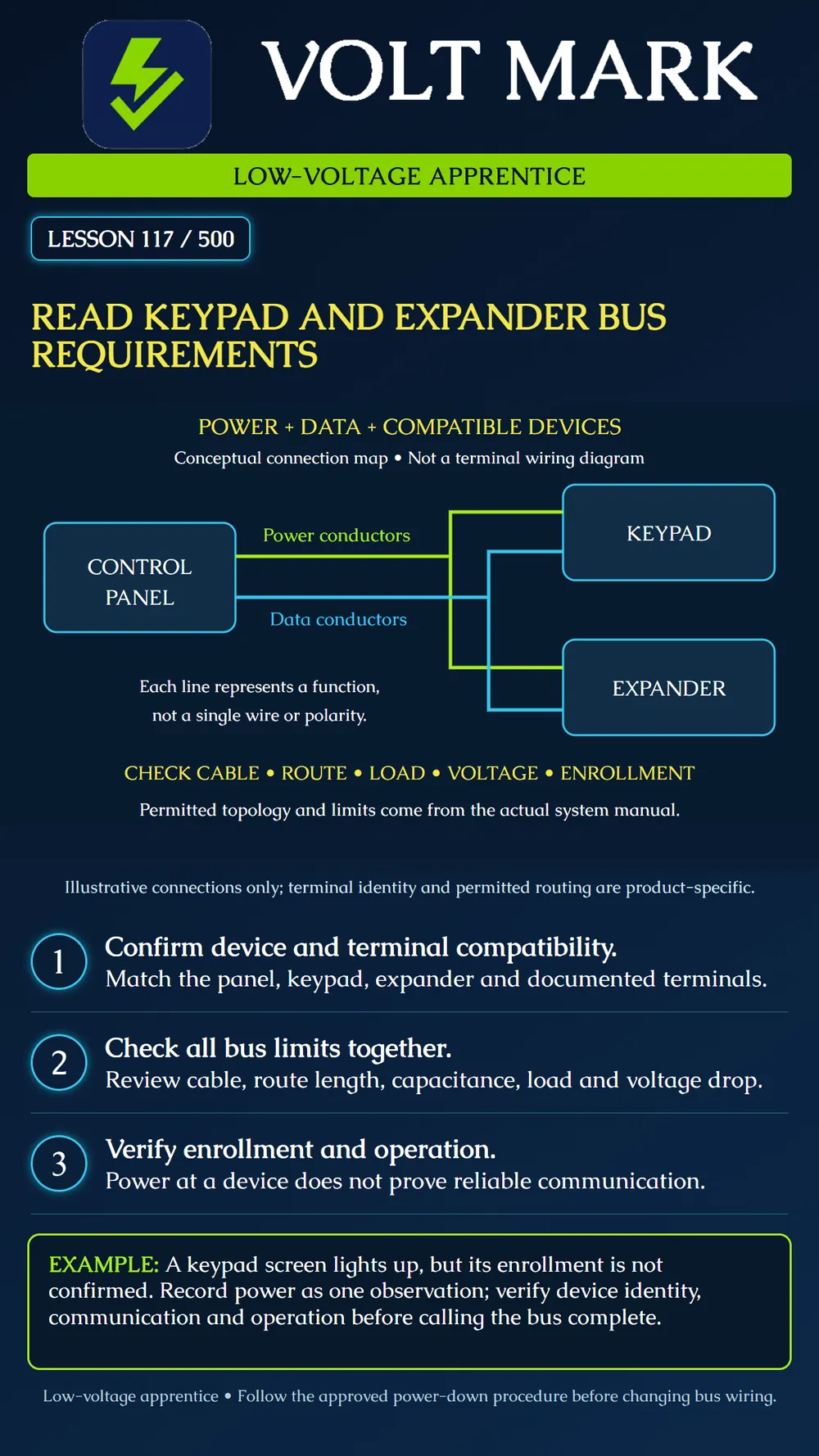
Read the requirements for a keypad and expander bus as a combined compatibility, wiring, power and communication problem.
A keypad or expander may share power and data connections with other devices, but a bus is not a generic four-wire interface. Confirm the exact panel, module family and documented compatible versions. Terminal labels and protocol matter; similar colors or connectors do not establish interchangeability.
DSC PowerSeries Pro Corbus documentation assigns RED and BLK to power and YEL and GRN to data. It specifies cable requirements and distance constraints, with an approved extender arrangement for longer applications. These are bounded examples, not universal rules for all alarm buses. Use the installed model's complete instructions for allowed topology, conductor selection and any shielding restrictions.
Several limits must be checked together. Route length to a device is different from total installed cable length. Cable capacitance affects data transmission, while resistance and current affect voltage at the load. A route that passes one check may fail another. The manufacturer's current calculation also requires considering combined loads rather than treating every terminal's maximum as independent available capacity.
Enrollment is another distinct step. PowerSeries Pro documentation provides module enrollment and a separate confirmation function. A powered keypad or illuminated module is not proof that it is recognized, assigned correctly or communicating reliably. Record the actual device identity and confirmed configuration.
The poster is a conceptual connection map. Each colored line represents a function, not a single conductor or polarity. It does not authorize the pictured branch arrangement for an arbitrary product. Obtain the approved terminal-level drawing before wiring.
A trainee sees a keypad display illuminate and marks the bus complete. The instructor asks for the module list and operating check. The display establishes only an observation of power and activity; enrollment and communication remain unverified. The record is corrected to show the separate checks still needed. No field test is claimed here.
Use an instructor-prepared training system and its current manuals. Collect the panel and device model numbers, supported firmware information where required, and an approved connection drawing. Create a device inventory before reviewing the cable.
For each route, record the actual cable specification, conductor size, route length and connection arrangement. Identify whether the manual limits individual runs, total bus cable, capacitance or several of these. Mark missing information UNKNOWN. Do not substitute straight-line room distance for installed wire length.
Build the required power worksheet using the manufacturer's specified operating states. Include relevant attached loads and shared supply limits. Have the instructor review the applicable voltage-drop method and minimum device voltage. Do not assume that a short route eliminates the need to check available current.
Before changing wiring, follow the approved power-down procedure for every relevant source, including standby power. Do not perform line-voltage work as part of this lesson. On the safe training setup, compare the actual terminal identities with the drawing. Never move conductors merely to match a familiar color scheme from another brand.
After authorized energization, confirm enrollment, identity and assignment using the product's procedure. Perform the required functional checks and review communication or supervision indications. Keep measured voltage, enrollment confirmation and operation results as distinct evidence.
Document discrepancies and have the responsible person approve corrections. Do not add an arbitrary power supply, join supply outputs or change bus routing as a guessed repair. Retest after approved changes and restore the documented final configuration.
Panel and module models / manual revisions: Compatibility evidence: Terminal mapping and approved topology: Cable type / conductor size / route lengths: Total cable or capacitance check, if applicable: Load calculation / shared supply limit: Device voltage evidence under required conditions: Enrollment identity / assignment / confirmation: Functional and communication results: Discrepancy / owner / retest / closeout:
Answer: No. Confirm terminal functions and supported equipment.
Answer: No. Confirm enrollment separately.
Answer: No. All applicable constraints must be satisfied.
Researched 2026-09-30, primary manufacturer documentation: DSC PowerSeries Pro Corbus wiring: https://docs.johnsoncontrols.com/dsc/r/DSC/en-US/PowerSeries-Pro-Reference-Manual/1.3.1/Installation/General-wiring-instructions/Corbus-wiring DSC PowerSeries Pro alarm controller current calculation: https://docs.johnsoncontrols.com/dsc/r/DSC/en-US/PowerSeries-Pro-Reference-Manual/1.3.1/Installation/General-wiring-instructions/Corbus-wiring/Alarm-controller-current-calculation DSC PowerSeries Pro enrolling modules: https://docs.johnsoncontrols.com/dsc/r/DSC/en-US/PowerSeries-Pro-Reference-Manual/1.3.1/Configuration/Enrollment/Enrolling-modules Original conceptual diagram, scenario, practice and record form. No universal bus dimensions or electrical limits asserted.
Free study material for low-voltage apprentices. This is a national foundation course: requirements differ by state and by local jurisdiction, and a practice that is common in one place is not a rule everywhere. Nothing here is a licence, a certification, or authority to work unsupervised, and completing it does not count as apprenticeship hours or continuing-education credit. Check the codes adopted where you are working, the licensing authority for that work, and your employer's safety programme. VoltMark is not affiliated with, endorsed by, or sponsored by NFPA, OSHA, NICET, BICSI, FOA, or any state or local licensing authority.

Electrician licensing exam prep: practice questions, timed exam simulations, and step-by-step help finding every answer in the NEC.