Terminate and inspect an instructor-approved intrusion training loop, keeping isolated resistance checks separate from powered functional verification.
Begin with the training system's exact wiring diagram and the instructor's approved exercise. Identify the zone input, return terminal, contact behavior and required supervision arrangement. A familiar-looking terminal is not enough to identify its function. Confirm the cable and device tags against the training record before preparing conductors.
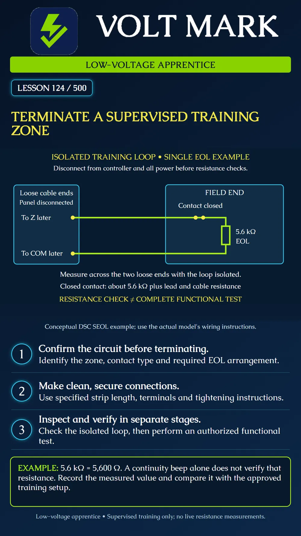
The poster shows an isolated loop: both cable ends are disconnected from the controller and no external power is connected. A closed contact and one resistor form a series path at the field end. The loose ends are labeled for their later destination, not shown connected to a powered panel. The drawing is conceptual rather than a terminal-by-terminal installation diagram.
The cited DSC PowerSeries Pro SEOL example uses a 5,600-ohm resistor at the end of the loop. Its documented table associates the closed-contact resistance with secure status and a short or open with alarm status. These are bounded product-example states; do not assume other systems use the same resistance or event classification.
Under qualified supervision, establish the de-energized training condition using the equipment procedure. Consider every source, including standby supplies. The manufacturer instructs that the controller be powered down for zone wiring. This poster does not teach a complete isolation procedure for every alarm installation.
Use the specified conductor preparation for the actual terminal. Strip only the instructed length with a tool suited to the conductor. Inspect for damage and escaped strands. Position the conductor so the terminal grips it correctly, without insulation preventing contact or excessive bare metal remaining exposed. Follow the manufacturer's tightening instructions and permitted conductor count. Do not invent a torque value, add unsupported ferrules or twist extra conductors into a terminal that is not rated for them.
At the field end, install the specified resistor and contact connections according to the approved diagram. Protect leads from unintended contact and strain using the permitted enclosure and connection method. Identify the cable at both ends. Leave the assembly arranged so the instructor can inspect the terminations before power is applied.
Trace the path shown: first loose end, outgoing conductor, closed contact, field-end resistor, return conductor, second loose end. There is no intentional bypass around the resistor. Have the instructor verify the actual arrangement against the approved wiring diagram.
With the loop isolated from the controller and all external power, use the meter as instructed to measure between its two loose ends. Record the instrument range, units and reading. The nominal resistor is 5.6 kΩ, equal to 5,600 Ω. The assembled closed-loop reading includes resistor tolerance and lead, connection and cable resistance. The supervisor establishes the acceptable result for the actual setup; the poster gives no universal acceptance band.
An audible continuity setting may not respond at this resistance. A beep or silence alone therefore does not establish the expected loop value. Read the resistance and its units. An unexpected result needs investigation before progressing.
If the instructor's exercise includes opening the training contact, record the changed resistance indication. An over-range display alone is not proof of the intended fault: wrong range or disconnected probes can also affect the reading. Check the instrument and setup rather than guessing.
After inspection and isolated measurements, the instructor determines whether the loop may be connected and the training controller configured and powered according to its instructions. Verify the intended input identity, response and restoration under the authorized exercise. Do not connect an ohmmeter across a powered input. No monitored-system test or live site change is authorized by this lesson.
Training panel/model; diagram revision; device and cable tags; zone and return; supervision mode; resistor specification/location; terminal instructions checked; inspection result; isolated measured resistance and units; instructor acceptance; separate functional test reference; unresolved issue.
Checked September 30, 2026: DSC / Johnson Controls, PowerSeries Pro Reference Manual 1.3.1, Single end-of-line resistor: https://docs.johnsoncontrols.com/dsc/r/DSC/en-US/PowerSeries-Pro-Reference-Manual/1.3.1/Installation/Installing-modules/Zone-wiring/Single-end-of-line-SEOL-resistor DSC / Johnson Controls, Zone wiring: https://docs.johnsoncontrols.com/dsc/r/DSC/en-US/PowerSeries-Pro-Reference-Manual/1.3.1/Installation/Installing-modules/Zone-wiring Product-specific resistor and supervision statements are limited to this manufacturer example. The drawing and practice workflow are original instructional material. Use actual terminal and meter manuals during practice.
Free study material for low-voltage apprentices. This is a national foundation course: requirements differ by state and by local jurisdiction, and a practice that is common in one place is not a rule everywhere. Nothing here is a licence, a certification, or authority to work unsupervised, and completing it does not count as apprenticeship hours or continuing-education credit. Check the codes adopted where you are working, the licensing authority for that work, and your employer's safety programme. VoltMark is not affiliated with, endorsed by, or sponsored by NFPA, OSHA, NICET, BICSI, FOA, or any state or local licensing authority.

Electrician licensing exam prep: practice questions, timed exam simulations, and step-by-step help finding every answer in the NEC.