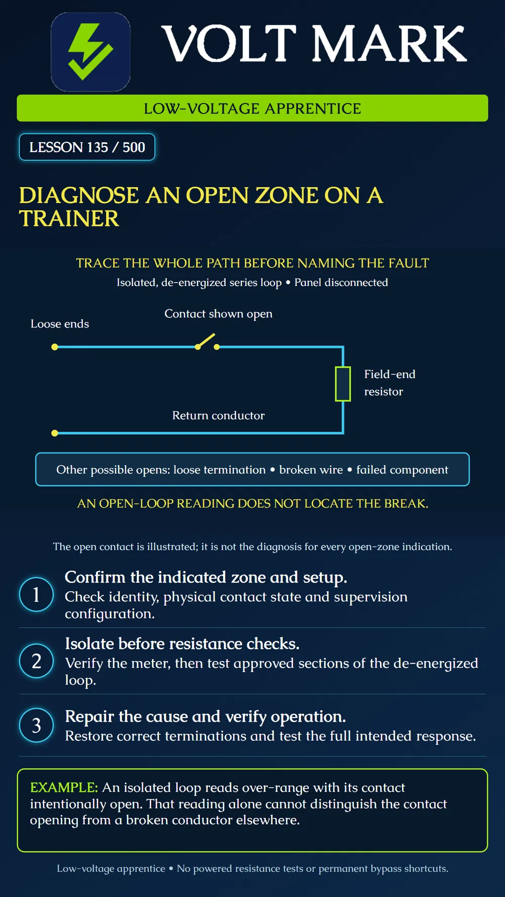
Investigate an open-zone indication on a supervised trainer by separating system interpretation, physical circuit state and evidence locating the fault.
First identify the actual zone and what the displayed condition means on that trainer. Confirm the device tag, input assignment, contact arrangement and supervision configuration. An open-zone indication is not automatically proof that the detector has failed.
Inspect the intended physical state. A door contact may be open because the door is open, the magnet is out of position or the contact arrangement differs from what was assumed. A loose connection, broken conductor or failed component can also interrupt a series path. Check the approved drawing and actual equipment rather than choosing one explanation from the display alone.
The cited DSC single-end-of-line example distinguishes its expected closed-loop resistance from an open circuit. Its interpretation belongs to that selected configuration. Other supervision modes can classify conditions differently. Do not assume every open circuit must appear as the same alarm, trouble or tamper event.
The poster shows two loose cable ends disconnected from a panel and all external power. A contact is intentionally drawn open in series with a field-end resistor. The return conductor runs back to the second loose end. The contact gap explains the illustrated open path, but it is not a diagnosis of an unknown trainer.
A resistance measurement across these loose ends cannot locate which series element is open. Multiple faults can produce an over-range indication. The selected meter range and probe contact also affect interpretation, so verify the instrument and connections before assigning a cause.
With the instructor, establish the approved de-energized condition, accounting for standby and other supplies. Identify and disconnect the training loop as required by the procedure. Resistance measurements must not be made on a powered input. Fluke's resistance guidance calls for circuit power to be off; use the actual meter manual and supervised isolation procedure.
Record the initial reading, range, units and contact state. An over-range display is not a precise measurement of infinite resistance. Confirm that the leads and selected function operate correctly using the instrument's approved checks.
Divide the circuit only at the instructor-approved test points. Compare an isolated section with its expected behavior. When necessary, separate components from parallel paths so another branch cannot conceal an open. Record where each reading was taken. A good reading across one section does not prove untested sections.
For a basic series trainer, the instructor may have you verify the contact's response in its intended states and check each isolated conductor end to end. The exact connection method depends on the trainer and test equipment. Do not improvise jumpers on a live panel or leave a resistor at the panel to make the zone appear normal.
The trainer is intentionally open at its contact. The first whole-loop reading is over-range. The instructor then places the contact in its approved closed state. If the expected loop resistance now appears, that change supports the contact-state explanation for this exercise. Still inspect and verify the complete intended operation before signoff.
In a second instructor-prepared case, the contact is closed but the whole-loop reading remains over-range. An isolated contact test shows the expected closed response. That narrows the investigation; it does not prove the cable is good. Continue with approved section checks until the evidence locates the interruption.
Repair only the confirmed issue using the specified parts and termination method. Inspect conductor condition, terminal security and the correct resistor location. Repeat the isolated checks appropriate to the repair.
After instructor approval, reconnect and operate the trainer according to its instructions. Verify the correct input identity, intended normal and activated responses, and restoration. Required reporting checks remain a separate coordinated step. Remove temporary test connections and record the final state.
If the physical loop readings agree with the design but the panel indication does not, escalate the input assignment, configuration and hardware investigation. Do not declare a wiring fault merely because it is the easiest explanation.
Trainer/model; drawing revision; indicated zone; actual device; supervision mode; expected physical state; isolation confirmation; meter/function/range; test-point pair; measured result; inference and remaining uncertainty; confirmed cause; correction; full-loop recheck; functional verification; final state.
Checked September 30, 2026: DSC / Johnson Controls, PowerSeries Pro, Single end-of-line resistor: https://docs.johnsoncontrols.com/dsc/r/DSC/en-US/PowerSeries-Pro-Reference-Manual/1.3.1/Installation/Installing-modules/Zone-wiring/Single-end-of-line-SEOL-resistor Fluke, How to Measure Resistance with a Digital Multimeter: https://www.fluke.com/en-us/learn/blog/digital-multimeters/how-to-measure-resistance The diagram and diagnostic cases are original training examples. No live measurements or actual repair results are claimed.
Free study material for low-voltage apprentices. This is a national foundation course: requirements differ by state and by local jurisdiction, and a practice that is common in one place is not a rule everywhere. Nothing here is a licence, a certification, or authority to work unsupervised, and completing it does not count as apprenticeship hours or continuing-education credit. Check the codes adopted where you are working, the licensing authority for that work, and your employer's safety programme. VoltMark is not affiliated with, endorsed by, or sponsored by NFPA, OSHA, NICET, BICSI, FOA, or any state or local licensing authority.

Electrician licensing exam prep: practice questions, timed exam simulations, and step-by-step help finding every answer in the NEC.