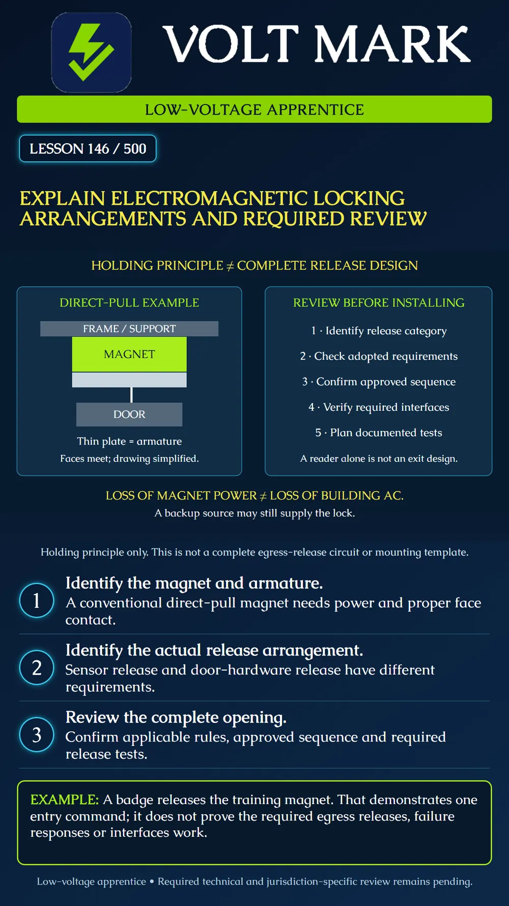
Explain the direct-pull magnetic holding principle and identify the information needed to review the complete release arrangement.
A conventional direct-pull electromagnetic lock holds a mating armature against its energized magnet face. The simplified diagram identifies the magnet, armature, supporting frame and door. It deliberately omits fasteners, brackets and electrical connections. Use the actual model's template and instructions for those details.
Securitron's M38/M68 instructions describe fail-safe electromagnetic locks and require unobstructed contact between the armature and lock face. The model's installation details matter: a plate that appears close is not evidence of the specified contact or mounting. Do not use this classroom sketch to select a bracket, drill an opening or assess a mounting surface's strength.
Holding and releasing are different design questions. Understanding that a conventional magnet requires power to hold does not establish how occupants obtain required egress. An entry credential command is only one possible input. The approved opening must provide its required release behavior independently of assumptions about how a user normally badges in.
Allegion's electromagnetic-lock guidance distinguishes sensor-release arrangements from arrangements released through door-mounted hardware. They have different applicable conditions. Other categories, including delayed or controlled egress, require their own review and are not taught as interchangeable wiring choices here. Determine the actual category and the adopted requirements before discussing a compliant sequence.
Do not assume that removing building AC removes power at the magnet. A battery-backed supply or another source may continue supplying it. Review the actual power architecture and required release paths. This lesson does not prescribe whether backup power is permitted for a particular installation or a universal method for disconnecting it.
Identify the opening, occupancy context, hardware models and proposed operating sequence. The responsible reviewer must establish the applicable adopted code edition, amendments, required approvals and product requirements. A generic online diagram cannot make those determinations for every state and county.
For the selected release arrangement, document the required normal egress operation, responses to relevant failures, manual releases and interfaces. Do not assume all electromagnetic locks require the same sensor, button, fire-alarm connection or timing. Conversely, do not omit a requirement because another opening used a different category.
The required verification plan should trace each applicable release condition to its expected physical result and evidence. Testing a credential transaction alone cannot prove an emergency or failure response. Coordinate any actual interface or power-interruption test through the approved site procedure.
An instructor uses an isolated demonstrator to show a magnet holding its mating plate. A permitted badge command releases it. A trainee writes "egress passed."
Revise that record. The evidence shows the demonstrated credential command caused the observed release on the trainer. It does not establish that a required sensor release, hardware release, manual release, loss-of-power response or other applicable interface was tested. The next task is to identify the approved release category and corresponding test plan, not to check every category indiscriminately.
In a second fictional review, a drawing contains a backup power supply but says only "unlock on power failure." Ask which power source and failure condition the designer means, and which release response is required. Record the ambiguity for authorized clarification. Do not resolve it by changing wiring or disabling backup power.
On an unpowered sample, identify magnet and armature and compare their documented roles. Use a supplied fictional design packet to locate the release category, operating sequence, power sources and review status. Mark each unresolved reference.
Create an evidence table with condition, required response, document reference, test method, observer and result. Leave unperformed tests marked not tested. Do not perform failure-mode demonstrations on an occupied exit as a classroom exercise.
Opening and hardware-set reference: Magnet / armature model and mounting documentation: Release arrangement category: Adopted requirements and reviewer: Approved operating-sequence reference: Power sources including backup: Required releases and interfaces: Planned test / expected result / evidence: Unresolved item / owner / disposition:
Does a successful badge release prove the complete egress design? No. Are sensor release and door-hardware release automatically the same arrangement? No. Does loss of building AC necessarily remove lock power? No. Can this drawing serve as a mounting template? No. Who resolves an ambiguous release sequence? The designated responsible designer or reviewer through the project process.
Primary sources checked September 30, 2026: Securitron, M38/M68 Installation and Operating Instructions, PN500-21400 RevC, May2012: https://www.securitron.com/content/dam/assa-abloy/americas/ems/securitron/document/AADSS1058197.pdf The manufacturer's hosted document supports bounded holding/contact principles; it is not asserted to be the current installation manual for every magnetic lock. Allegion / Lori Greene, ShortCodes5C, Electromagnetic Locks: https://idighardware.com/shortcodes/shortcodes-5c/ Allegion / Lori Greene, Electrified Hardware and Special Locking Arrangements: https://idighardware.com/sla/ Original diagram and exercises explain review questions, not a complete code-compliant circuit. No actual opening was tested or approved.
Free study material for low-voltage apprentices. This is a national foundation course: requirements differ by state and by local jurisdiction, and a practice that is common in one place is not a rule everywhere. Nothing here is a licence, a certification, or authority to work unsupervised, and completing it does not count as apprenticeship hours or continuing-education credit. Check the codes adopted where you are working, the licensing authority for that work, and your employer's safety programme. VoltMark is not affiliated with, endorsed by, or sponsored by NFPA, OSHA, NICET, BICSI, FOA, or any state or local licensing authority.

Electrician licensing exam prep: practice questions, timed exam simulations, and step-by-step help finding every answer in the NEC.