Calculate shared startup and holding demand from supplied loads and explain why a steady-current total alone cannot approve a power supply.
All values below are fictional teaching inputs, not ratings of a named product. Supply rail:24VDC. Two identical lock loads. Each lock total startup current:1.20A for0.50s. Each lock holding current after startup:0.30A. Other shared load:0.30A constant throughout. Both locks begin startup together.
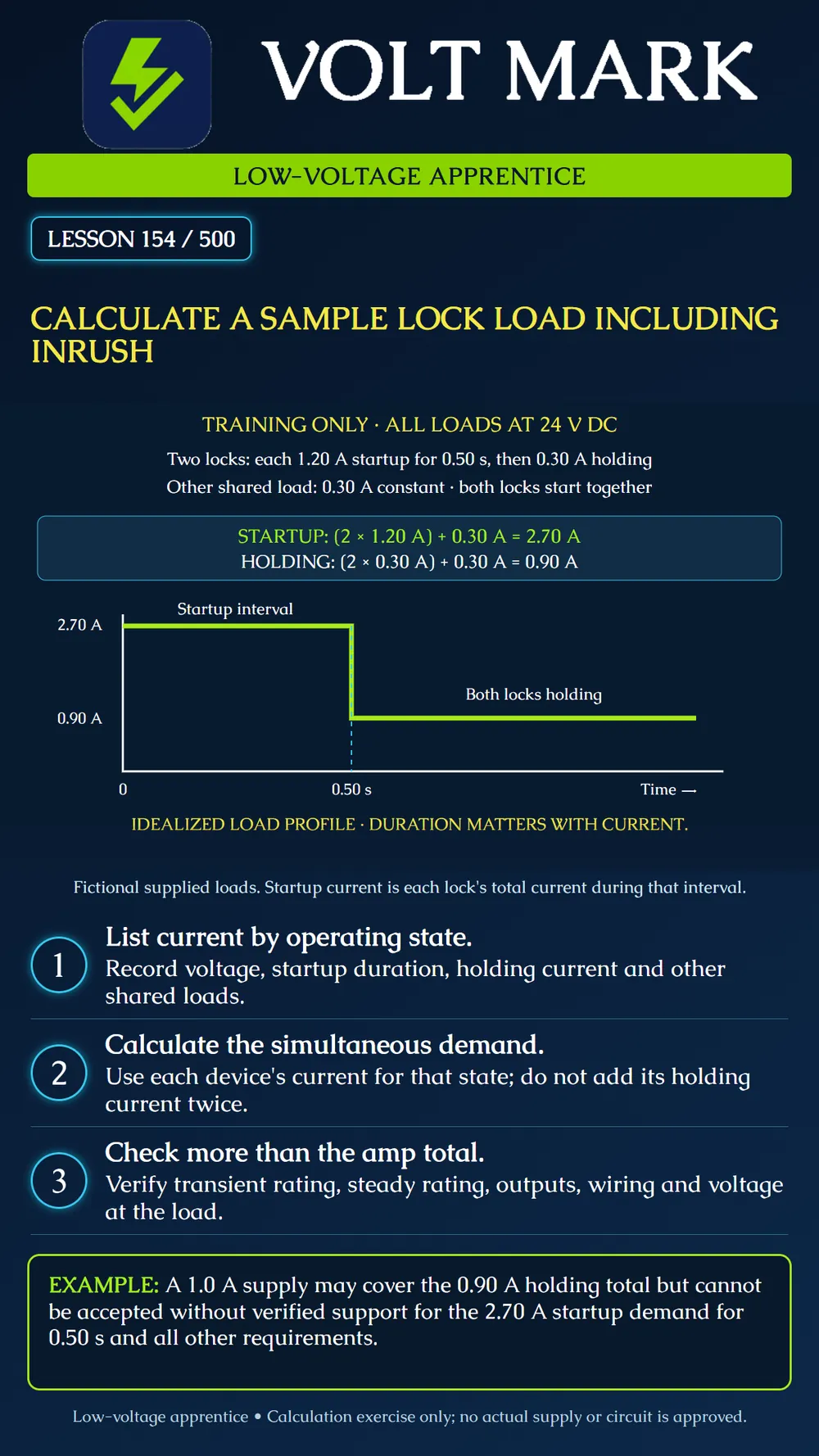
During simultaneous startup: I = 1.20A + 1.20A + 0.30A = 2.70A. That demand lasts0.50s in this idealized example.
After both locks transition to holding: I = 0.30A + 0.30A + 0.30A = 0.90A.
The graph represents these two states beginning when both locks start. It is not an oscilloscope trace and does not show the pre-start current or every possible transient shape. Its horizontal break occurs at the supplied0.50s interval.
Some electrified hardware draws more current while initiating movement or retracting a latch than it uses to maintain the resulting state. Manufacturer guidance therefore distinguishes startup or inrush from holding current and asks how long the startup demand lasts.
Use the total current for each device in the state being evaluated. In this exercise,1.20A is the whole startup current for one lock. It is not an additional1.20A on top of the0.30A holding value. Adding holding again during that interval would count part of the same device twice.
Keep other simultaneous loads in the calculation. The constant0.30A load remains present during startup and holding. A design calculation that considers only the locks would miss it.
A supply whose steady rating exceeds0.90A is not automatically suitable. It must support the documented startup demand for the required duration while maintaining the specified output, and the rest of the circuit must also meet its requirements. A nominal ampere label without the relevant transient specification is incomplete evidence.
Verify the voltage required by every load on the rail. Identify which loads share the supply and which share an individual output. Confirm per-output and aggregate ratings, distribution-board limits, switching-device suitability, protection and cable voltage drop. The equipment must receive acceptable voltage during the relevant operating states, not just when unloaded.
If a supply has a documented transient allowance, compare both current and duration and any stated repetition or recovery conditions. Do not assume that a momentary peak rating can be used continuously. Conversely, do not reject or accept a supply only by comparing peak current with its steady label; use the actual manufacturer specifications.
The two-lock example makes no allowance for battery charging, additional loads, environmental derating or design reserve. Include applicable requirements in the real project review rather than inventing a universal percentage.
A trainee sees0.90A holding demand and proposes a1.0A supply. The available sheet does not document transient support. The correct disposition is not proven suitable: the2.70A demand for0.50s remains to be addressed, together with the other circuit requirements.
A second trainee proposes staggering the locks to reduce peak demand. That changes the operating sequence and cannot be assumed acceptable. Only a documented, approved sequence may be used in a design calculation. If both can start together under any required condition, account for that condition.
Under a separately supplied hypothetical condition where one lock is starting and the other is already holding: 1.20A + 0.30A + 0.30A = 1.80A. This does not replace the2.70A simultaneous-start case. It illustrates why the state of every load must be named.
At an ideal24V output, the main example corresponds to64.8W during startup and21.6W during holding. These are output-load calculations, not AC input power, efficiency, battery runtime or supply-selection approvals.
Recalculate the two main states with units. Mark the startup interval on a blank graph and explain why holding current is not added twice. Then compare a supplied fictional power-supply data sheet with the current, duration and voltage requirements. List any information missing before selection can be completed.
Do not wire a live opening or interrupt egress equipment to create this classroom exercise. Actual measurement and commissioning require the approved procedure and appropriate instruments.
Simultaneous startup total?2.70A. Holding total?0.90A. Startup duration?0.50s. Is1.20A added to the same lock's0.30A holding value during startup here?No. Can staggering be assumed without an approved sequence?No.
Primary manufacturer guidance checked September30,2026: Von Duprin, Power Supplies101: https://www.vonduprin.com/en/resources/training-education/von-duprin-101/power-supplies.html Source supports considering startup current, duration, other loads and operating sequence. The numerical data, graph, scenarios and calculations are original fictional exercises. Product-specific QEL ratings were not used because actual model/revision documentation must govern them.
Free study material for low-voltage apprentices. This is a national foundation course: requirements differ by state and by local jurisdiction, and a practice that is common in one place is not a rule everywhere. Nothing here is a licence, a certification, or authority to work unsupervised, and completing it does not count as apprenticeship hours or continuing-education credit. Check the codes adopted where you are working, the licensing authority for that work, and your employer's safety programme. VoltMark is not affiliated with, endorsed by, or sponsored by NFPA, OSHA, NICET, BICSI, FOA, or any state or local licensing authority.

Electrician licensing exam prep: practice questions, timed exam simulations, and step-by-step help finding every answer in the NEC.