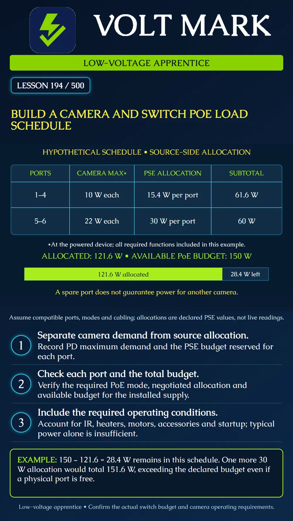
Prepare a camera power schedule that distinguishes powered-device demand, source-side allocation, per-port compatibility and total available PoE budget.
The camera is the powered device, or PD. The switch or midspan supplying power is power sourcing equipment, or PSE. Cable losses mean these are not identical power measurement points. Axis distinguishes typical camera consumption from maximum consumption and notes that typical figures can exclude heaters and IR. The required operating functions and cable losses belong in planning. A daytime reading with major loads inactive is not proof of adequate nighttime capacity. Cisco's cited guide shows that negotiation, port settings and budget policy affect allocation. Its exact behavior is product-specific; do not apply its configuration details to every switch.
Assume the required camera modes, source ports and cabling are compatible. The available PSE budget is declared as 150 W for the installed supply and conditions. The instructor supplies these allocation values: Ports 1–4: four cameras, each with a stated 10 W maximum at the PD and 15.4 W allocated at the PSE. Ports 5–6: two cameras, each with a stated 22 W maximum at the PD and 30 W allocated at the PSE. All required camera functions are included in the hypothetical maximum values. This is not a selection of real products or a universal allocation policy.
Four allocations at 15.4 W = 61.6 W. Two allocations at 30 W = 60 W. Total PSE allocation = 121.6 W. Unallocated budget = 150 - 121.6 = 28.4 W. The camera-side maximum sum is 4 × 10 + 2 × 22 = 84 W. It is a different quantity and must not replace the stated allocation total when assessing this example's reservation budget. Do not add a second arbitrary cable-loss percentage to an allocation already specified at the source. Understand the basis first.
A proposed seventh camera requires another 30 W source allocation under the declared policy. 121.6 + 30 = 151.6 W. That exceeds 150 W by 1.6 W. A free socket does not solve the budget shortfall. A low current reading on another port does not automatically release its reserved allocation. Resolve the actual design or allocation evidence; do not switch off required heaters or illumination merely to make the arithmetic fit.
For an actual project, record port number, camera identifier, exact model, required PoE type/class or mode, maximum PD demand with source reference, PSE allocation basis, supported per-port capability and special loads. Add cable-path information, negotiation evidence and relevant startup requirements. A grouped table is useful for this poster, but the field schedule should preserve individual port assignments. Include other powered equipment on the same switch. The switch's AC supply nameplate is not automatically the power available to PoE ports.
Use documentation for the installed power supply arrangement, redundancy mode, temperature and any shared power pool. Determine what happens to the available budget in the conditions the project requires, including a specified supply-loss scenario. Do not assume every port can deliver its advertised maximum simultaneously. Conversely, do not invent a lower budget where the manufacturer's actual configuration provides sufficient capacity. Record any required reserve separately and identify its source. The 28.4 W figure above is unallocated arithmetic balance, not a universal engineering margin or automatic approval for growth.
The cameras run in a warm room but some restart when outdoor heating and IR become active. Compare the approved schedule with the actual negotiated mode, port allocations, logs and relevant operating conditions. Review required loads rather than concluding that a network outage explains every restart. Use authorized tests and product-supported diagnostics. A brief meter peak or a quiet daytime average may not capture the required operating case. No live device settings or power connections are changed in this lesson.
Keep planned maximum demand, reserved allocation and measured consumption in separate columns. Record the source of each number. For unresolved values, assign an evidence request rather than inserting a convenient typical value. Update the schedule after an approved camera replacement, accessory addition or switch supply change. Preserve the prior revision so the reason for the new load is traceable.
Axis, Typical and maximum power consumption in Axis cameras: https://whitepapers.axis.com/en-us/typical-and-maximum-power-consumption-in-axis-cameras Basis: measurement conditions, maximum functions and source/cable-loss distinction. Cisco, Guidelines for PoE: https://www.cisco.com/c/en/us/td/docs/switches/lan/c9000/infra/poe/poe-configuration-guide/g-poe/r-guidelines-for-poe.html Basis: allocation, negotiation and budget policy examples, bounded to the documented product family. All camera demands, assignments and the 150 W budget are invented teaching inputs.
Free study material for low-voltage apprentices. This is a national foundation course: requirements differ by state and by local jurisdiction, and a practice that is common in one place is not a rule everywhere. Nothing here is a licence, a certification, or authority to work unsupervised, and completing it does not count as apprenticeship hours or continuing-education credit. Check the codes adopted where you are working, the licensing authority for that work, and your employer's safety programme. VoltMark is not affiliated with, endorsed by, or sponsored by NFPA, OSHA, NICET, BICSI, FOA, or any state or local licensing authority.

Electrician licensing exam prep: practice questions, timed exam simulations, and step-by-step help finding every answer in the NEC.