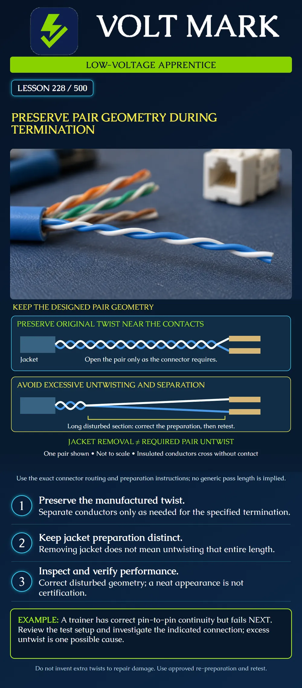
Recognize unnecessary disturbance of a balanced pair near a connector, distinguish jacket removal from pair untwisting and inspect the finished geometry under the exact product instructions.
Balanced-pair cabling uses controlled conductor geometry to help manage electromagnetic coupling. Pair twist rates are part of the cable design; different pairs can have different rates. Straightening an unnecessarily long section changes that geometry near the connector. The objective is to preserve the designed construction, not to add as many twists as possible. [1]
The top sketch keeps the pair twisted near the contact area and opens it only for the final connection. The lower sketch deliberately shows an unnecessarily long separated section. Both are conceptual, not to scale and not physical IDC-location drawings. White and blue represent two insulated conductors of one pair. Their crossings do not indicate electrical connections. A real jack or plug may use a lacing guide, separate pair channels, a loading bar or another arrangement. Follow its geometry rather than copying the shape of this sketch.
The outer jacket may be removed over a preparation length while the individual pairs remain twisted. Therefore, a jacket-strip dimension is not permission to straighten the pairs over that whole distance. For example, Siemon's Flat MAX instructions describe lacing features that can retain pair twist, with a construction-specific exception for bonded pairs. They specify how to route the cable and assemble that product. This reinforces the need to follow the actual termination hardware and cable combination. [2]
Connector instructions control preparation and termination. Fluke's troubleshooting guidance notes that excessive untwist can contribute to NEXT failures and that a commonly cited 13 mm value is not a guarantee of passing performance. Its discussion references a historical standards edition, not a nationwide current-code requirement. [3] This lesson deliberately does not turn one dimension into a target for every category and connector. Use the documented requirements, preserve as much original geometry as the correct assembly permits, and perform the required tests.
The instructor provides two disconnected samples of the same cable and connector type. One was prepared according to the instructions. The other has its pairs unnecessarily spread out over a long exposed section. Before testing, the learner records:
Do not mark either sample electrically accepted from a photograph. Compare the visible construction with the instructions, then record the actual test results. Keep damaged practice samples segregated from usable materials.
A learner straightens all eight conductors into a wide fan because it makes the colors easy to see. The jack cap closes and the work looks tidy. Ask whether the fan was required by the product's lacing method. If not, the visual neatness is not a reason to keep it. Re-prepare or replace the sample using the approved procedure and sufficient available cable. Do not hide excessive separation beneath a cover and treat it as corrected.
Do not attempt to compensate by winding extra turns into the separated conductors. The goal is to return to an approved preparation, not create a new twist pattern. Have the instructor determine whether enough undamaged cable and a reusable connector remain for retermination. Otherwise replace the affected training material. Also avoid pulling the individual conductors tight to close a cover. The final assembly should follow the specified routing and support without distortion.
Sample ID: Cable / connector: Specified preparation: Visible deviations: Tester and setup: Initial result: Confirmed defect, or “cause not confirmed”: Approved correction: Retest report: Instructor assessment:
The record distinguishes observation, interpretation and measured evidence. “Looks better” is an observation; it is not the same as a passed certification report.
Mistake: Untwisting every pair for the full jacket-strip distance. Correction: Treat jacket removal and pair separation as different dimensions and follow the connector's lacing method.
Mistake: Adding extra turns to compensate for a long straightened section. Correction: Have the instructor approve fresh preparation or replacement that preserves the original construction rather than inventing a twist pattern.
Mistake: Calling excessive untwist the confirmed cause of every NEXT failure. Correction: Check the limit, adapters and diagnostic evidence, inspect the indicated region and record the actual finding before assigning a cause.
Why can a tidy conductor fan still be unacceptable?
Answer: Visual order does not establish the required pair geometry; compare it with the exact product's routing instructions.
Why does a correct wire map not settle NEXT performance?
Answer: Mapping checks endpoint connections, while NEXT evaluates unwanted signal coupling between pairs.
[1] Fluke Networks, The Physics of Twisted Pair Cabling. https://www.flukenetworks.com/blog/cabling-chronicles/physics-twisted-pair-cabling [2] Siemon, Punchdown Flat MAX Module Instructions, Rev. D 07/07, 100.12450. https://files.siemon.com/en/instruction/wa_punchdown-flat-max-module_ii.pdf [3] Fluke Networks, NEXT (Near-End Crosstalk) Troubleshooting. https://www.flukenetworks.com/knowledge-base/dtx-cableanalyzertm/next-near-end-crosstalk-troubleshooting Historical document examples do not replace current product instructions or adopted project requirements.
Texas journeyman, 15 questions, scored by topic against the 70% mark. No card, and no account needed to start.
Free study material for low-voltage apprentices. This is a national foundation course: requirements differ by state and by local jurisdiction, and a practice that is common in one place is not a rule everywhere. Nothing here is a licence, a certification, or authority to work unsupervised, and completing it does not count as apprenticeship hours or continuing-education credit. Check the codes adopted where you are working, the licensing authority for that work, and your employer's safety programme. VoltMark is not affiliated with, endorsed by, or sponsored by NFPA, OSHA, NICET, BICSI, FOA, or any state or local licensing authority.

Electrician licensing exam prep: practice questions, timed exam simulations, and step-by-step help finding every answer in the NEC.