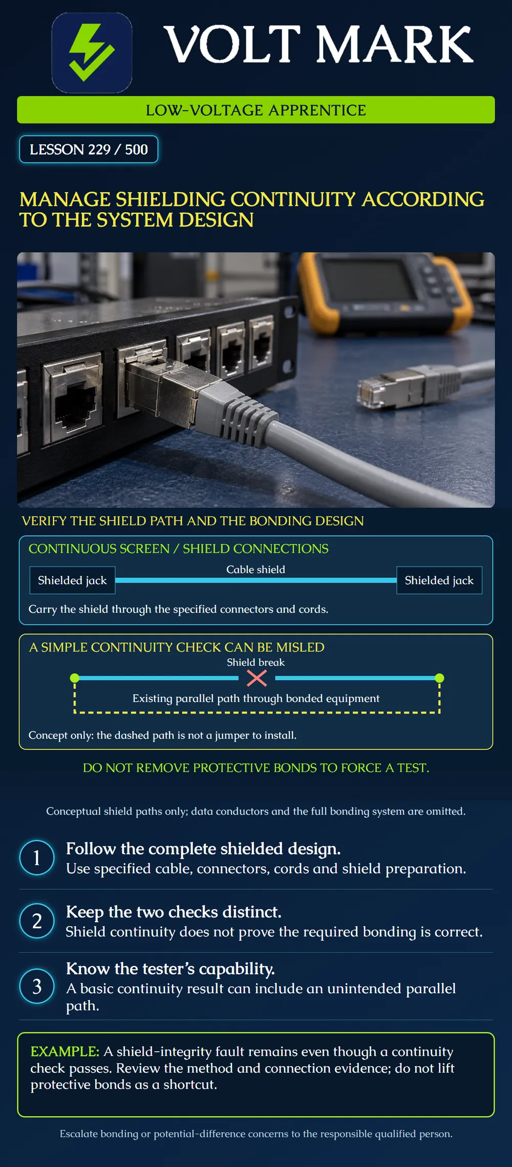
Trace the intended shield path, distinguish it from the facility bonding arrangement and interpret continuity evidence within the test method's limits. This lesson concerns shielded balanced-pair structured cabling. It does not prescribe one shield-termination rule for every control, audio, fire alarm or other low-voltage circuit.
A screen/shield connection continues the cable's shielding through compatible connecting hardware. The grounding/bonding arrangement connects the system to the designated facility infrastructure. Siemon distinguishes these functions and recommends maintaining shielding through the complete specified cabling system, including cords. Its discussion also recognizes equipment-end ground paths; it does not support a universal rule to deliberately break the far-end shield. [1]
The drawing is a conceptual shield-path diagram. The horizontal cyan line is not a data conductor, a drain-wire installation instruction or a protective grounding conductor. Actual construction can include foil, braid and drain arrangements that require product-specific preparation.
Identify the cable construction and the exact connector's instructions. Confirm the specified shielded jacks, plugs, panel interfaces and cords throughout the intended path. Preserve the designed shielding at each interface rather than merely keeping a visible piece of foil. Document the bonding provisions separately: what is to be bonded, to which designated point, by which approved method and under whose responsibility. Do not assume a metal faceplate, painted rack contact or continuity beep proves that the complete bonding design was installed correctly.
A simple DC shield-continuity check can find a route through already bonded equipment or building infrastructure even when the intended cable shield is open. Fluke describes a DSX shield-integrity method that distinguishes such faults and provides diagnostic location information. Use the supported instrument, adapters and configuration for the job; not every tester implements that method. [2] The dashed path in the lower drawing represents a possible existing alternate route. It is not a suggested jumper. Do not disconnect protective bonds to make a reading change.
The training work order requires a shielded channel. A learner replaces a specified shielded cord with an unshielded cord because the plug fits and the device links. Record the substitution against the design. A working application does not establish that the specified shield path remains intact. Obtain an approved compatible cord or a documented design decision. Do not hide the substitution by calling the entire channel shielded simply because most of the installed cable has foil.
Two reports appear inconsistent. One shows basic shield continuity; another, using an appropriate shield-integrity method, indicates an open near a connection. First verify that both reports refer to the same cable and configuration. Review instrument capabilities, setup and the indicated location. Inspect the accessible termination under the authorized disconnected-work procedure and exact product instructions. An alternate path is a possible explanation, not proof of a specific damaged connector. Record the confirmed finding and any correction, then perform the required retest. If the evidence remains unclear, escalate rather than disconnecting bonds or changing acceptance limits.
A plug has a metal body, but the cable's shield was not prepared or engaged according to its instructions. The learner claims the metal body makes the connection shielded. The correct response is to inspect the actual shield interface. Appearance alone does not establish contact, coverage or performance. Correct or replace the assembly under the manufacturer's method. Do not improvise a long drain-wire extension to create an apparent continuity path.
This lesson does not tell the apprentice to bond every shield at both ends, nor to isolate every far end. Use the system design and the relevant manufacturer instructions for the actual application. Structured-cabling guidance cannot simply be copied onto a different signaling circuit. Unexpected potential differences, damaged bonding components or suspected electrical faults require the responsible qualified person's review. A cable shield is not a substitute for required protective bonding. The apprentice's role is to recognize and document the condition, not redesign the facility grounding arrangement.
System and cable ID: Applicable design / drawing revision: Cable and connector parts: Shield preparation instruction: Cords and intermediate interfaces: Designated bonding provisions: Visual inspection findings: Instrument / adapters / configuration: What the measurement actually evaluates: Result, fault location estimate and report: Confirmed repair and retest: Outstanding questions and responsible person:
Keep “observed shield connection” separate from “bonding verified.” Keep a limited continuity result separate from full performance certification. The final record must state what was actually inspected and measured.
A fictional shielded-channel review supplies a basic continuity pass, a correctly configured shield-integrity report indicating an open near one end, and a parts list showing an unshielded substitute cord. Write two separate evidence issues and the next authorized action for each.
Answer: The cord conflicts with the specified channel construction and needs an approved replacement or design resolution. The apparently conflicting reports need matching cable IDs, configurations and method review, followed by inspection of the indicated accessible termination under the disconnected-work plan. The substitution is documented evidence, but it does not by itself prove the exact cause of the reported open. Preserve both reports; do not disconnect protective bonds as an experiment.
Mistake: Replacing a specified shielded cord with an unshielded cord because the device links. Correction: Record the design mismatch and obtain the approved compatible cord or an authorized design decision.
Mistake: Treating a basic continuity beep as proof of the intended shield route. Correction: Identify what the test measures and use the supported shield-integrity method where required; an existing alternate route can influence a DC check.
Mistake: Removing a protective bond to make an unexpected shield reading disappear. Correction: Preserve the reading and refer the bonding/test question to the responsible qualified person without disturbing protective connections.
Does a metal plug body prove that its shield interface was assembled correctly?
Answer: No. The actual cable-shield contact and preparation must follow the specific connector method.
Why keep facility bonding separate from the shield result?
Answer: A cable measurement does not verify the complete designated bonding arrangement or its installation requirements.
[1] Siemon, Screened and Shielded Cabling: Noise Immunity, Grounding, and the Antenna Myth, particularly Grounding and Cabling Systems. https://files.siemon.com/en/whitepaper/22-05-11-shielded-myth.pdf [2] Fluke Networks, Shield integrity test – DSX CableAnalyzer. https://www.flukenetworks.com/knowledge-base/dsx-cableanalyzer-series/shield-integrity-test-dsx-cableanalyzer Historical standard references are not presented as current locally adopted requirements. Tester behavior is method-specific, not a claim that every modern wire-map tester is identical.
Texas journeyman, 15 questions, scored by topic against the 70% mark. No card, and no account needed to start.
Free study material for low-voltage apprentices. This is a national foundation course: requirements differ by state and by local jurisdiction, and a practice that is common in one place is not a rule everywhere. Nothing here is a licence, a certification, or authority to work unsupervised, and completing it does not count as apprenticeship hours or continuing-education credit. Check the codes adopted where you are working, the licensing authority for that work, and your employer's safety programme. VoltMark is not affiliated with, endorsed by, or sponsored by NFPA, OSHA, NICET, BICSI, FOA, or any state or local licensing authority.

Electrician licensing exam prep: practice questions, timed exam simulations, and step-by-step help finding every answer in the NEC.