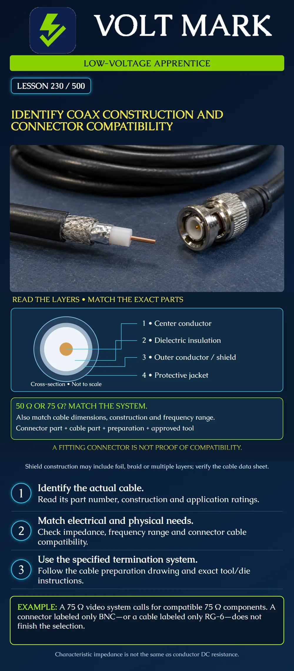
Identify the layers of coaxial cable and compare the exact cable, connector and termination method with the system requirements. This lesson covers communications and video cabling selection; it does not authorize work on active RF transmitters or powered coax systems.
The center conductor runs along the cable axis. Dielectric insulation separates it from the surrounding outer conductor/shield. The jacket protects the assembly. The outer conductor is part of the coaxial transmission structure, not simply spare metal to remove. Its construction may include foil, braid or multiple shield layers. The poster shows a simplified circular cross-section. It does not show strip lengths, connector insertion depth or every possible shield construction.
Belden 1694A is one documented example: nominal 75-ohm RG-6 SDI coax with an 18 AWG solid bare-copper center conductor, foamed polyethylene insulation, foil plus tinned-copper braid shielding and a PVC jacket. Its data sheet lists nominal dielectric diameter of 4.57 mm and overall diameter of 6.96 mm. These are different dimensions for one named cable; they are not universal RG-6 dimensions. [1]
The apprentice should be able to point to the relevant line in the data sheet rather than answer from jacket color. A complete part identification matters more than a visual resemblance to the last reel used.
Amphenol RF supplies BNC connectors in both 50-ohm and 75-ohm versions. Therefore, “BNC” does not by itself identify the electrical match. [2] Match the system's nominal characteristic impedance and specified frequency/application performance, along with the mechanical interface. Characteristic impedance describes transmission-line behavior; it is not the center conductor's ordinary DC resistance. An ohmmeter continuity reading does not identify a cable as 50 or 75 ohms. The Belden sheet lists conductor DC resistance separately from nominal characteristic impedance. [1]
A connector must suit the intended cable construction and dimensions, including the center contact, dielectric, shield and jacket arrangement. Use the manufacturer's cable compatibility information and assembly drawing for the exact part. For example, Amphenol's 031-80103 is identified as a 75-ohm BNC straight crimp plug for specified RG-59/RG-62 cable types. That listing is not approval for the different RG-6 example above. [3] These source examples illustrate selection questions; they are not a recommended cable-and-connector kit.
The supported termination may use crimping, compression, soldering or another method. Follow its designated preparation and tooling. A compression tool is not automatically a substitute for a crimp tool, and an arbitrary crimp die is not accepted merely because it closes around the ferrule.
The work card for a disconnected video trainer calls for a 75-ohm system. A bag of connectors says only “BNC,” and the connector part number cannot be found. Record the identification gap. Obtain the part information before assembly. Do not call the connector suitable because the bayonet locks onto the equipment. Mechanical engagement does not complete the electrical or cable-construction checks.
Two reels carry an RG-6 description but have different manufacturer part numbers. The apprentice wants to use the same connector and preparation tool without checking. Compare both data sheets and the connector's supported cable list. Verify conductor material and size, dielectric and jacket dimensions, shield layers and application requirements. If the combination is not supported or remains uncertain, get manufacturer confirmation or an approved alternative. Do not shave the dielectric, remove extra shield layers or force the ferrule to make an unidentified combination fit.
A component is nominally 75 ohms, but no evidence establishes its required frequency range or the proposed cable length's loss performance for the video format. Mark that selection pending. Matching impedance is necessary for the specified system, but it is not the complete application qualification. This lesson does not give one maximum coax distance for all formats. Use the relevant cable loss data, equipment limits and system design.
Required application and nominal impedance: Cable manufacturer and exact part: Center conductor material, size and construction: Dielectric type and diameter: Shield construction: Overall diameter and jacket/environment rating: Connector manufacturer and exact part: Explicit cable compatibility evidence: Required frequency/application performance: Preparation drawing and revision: Tool, die or compression setting: Unresolved requirements and responsible reviewer:
Keep environmental and pathway requirements separate from connector fit. Neither an RG designation nor a connector family name alone establishes suitability for a plenum, wet location or other installation condition.
A fictional 75-ohm trainer uses documented Belden 1694A cable. Connector A is labeled only BNC. Connector B is documented as 75 ohms but its supplied compatibility list covers a different cable family. No further approval is supplied. Build an evidence row for each connector: known property, missing property and next action.
Answer: A lacks exact identity, impedance and cable-compatibility evidence; obtain the part data before assembly. B establishes one electrical property but not compatibility with 1694A; obtain explicit manufacturer support or an approved compatible part. Do not force the ferrule, alter dielectric dimensions or remove shield layers to make the combination fit. Neither proposed kit is approved by these facts.
Mistake: Approving a BNC part from bayonet fit alone. Correction: Find its exact part number and verify nominal impedance, application range and supported cable construction.
Mistake: Applying one preparation setup to every reel marked RG-6. Correction: Compare the actual conductor, dielectric, shield and jacket dimensions with the connector's supported cable list and assembly drawing.
Mistake: Using a DC continuity reading to label a cable 75 ohms. Correction: Obtain characteristic impedance from the product specification; record continuity and conductor DC resistance as different measurements.
Why are 4.57 mm and 6.96 mm not interchangeable in the named cable example?
Answer: They describe dielectric diameter and overall cable diameter, which affect different connector interfaces.
Why does matching impedance leave work to do?
Answer: Cable fit, frequency/application performance, length loss and installation requirements still need their own evidence.
[1] Belden 1694A Technical Data Sheet, revision 0.716, 2026-05-27. https://catalog.belden.com/techdata/EN/1694A_techdata.pdf [2] Amphenol RF, BNC RF Connectors, 50 and 75 Ohm Coaxial Connectors. https://www.amphenolrf.com/en-us/products/rf-connectors/bnc-connectors/ [3] Amphenol RF, 031-80103 BNC Straight Crimp Plug. https://www.amphenolrf.com/en-us/part/031-80103/2135/ Product examples are separate; no compatibility between them is claimed.
Texas journeyman, 15 questions, scored by topic against the 70% mark. No card, and no account needed to start.
Free study material for low-voltage apprentices. This is a national foundation course: requirements differ by state and by local jurisdiction, and a practice that is common in one place is not a rule everywhere. Nothing here is a licence, a certification, or authority to work unsupervised, and completing it does not count as apprenticeship hours or continuing-education credit. Check the codes adopted where you are working, the licensing authority for that work, and your employer's safety programme. VoltMark is not affiliated with, endorsed by, or sponsored by NFPA, OSHA, NICET, BICSI, FOA, or any state or local licensing authority.

Electrician licensing exam prep: practice questions, timed exam simulations, and step-by-step help finding every answer in the NEC.