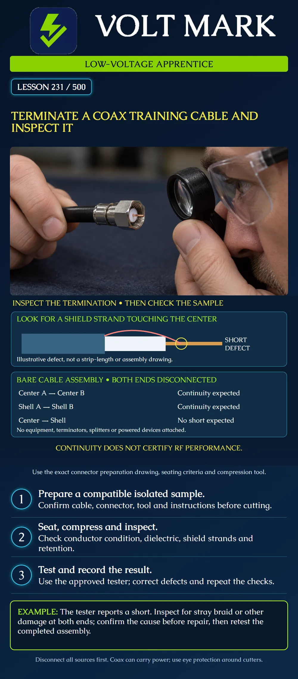
Prepare, terminate and inspect a disconnected coax training sample using a supported compression F-connector system, then record the limits of the electrical checks performed.
Use a known RG6/6Q sample that meets the connector's compatibility requirements, the appropriate Klein Universal F connector and a manufacturer-supported compression tool. The VDV002-818 kit is a documented example containing VDV812-606 connectors, a VDV110-061 stripper, a VDV212-008 compression tool and a Coax Explorer 2. Its tester checks continuity and identifies good/open/short conditions. [1] This example does not approve every cable bearing an RG6 label. Apply Lesson 230's exact-part and dimensional checks before the instructor selects the actual sample.
Use a bench cable disconnected at both ends from equipment, splitters, terminators, antennas, power inserters and all other systems. Coax may carry DC power or RF energy; an unknown installed cable is not a practice sample. The instructor establishes the disconnected boundary and required precautions. Wear eye protection, keep fingers out of cutters and collect small braid and conductor fragments. Do not place a connector in powered equipment to find out whether the termination is correct.
Klein's connector instructions use a stepped strip, fold the wire shield over the jacket, specify insertion until the center conductor projects approximately 1/8 inch (3 mm) beyond the connector, and then compress the assembly. [2] Use Figure 1 of the actual instructions for the individual stripping dimensions. The final projection is not a jacket-strip length. Do not copy an unrelated BNC or compression connector's preparation. Follow the cable-specific treatment for foil and multiple shields; this lesson does not authorize removing every shield layer.
The overview supports the original connector instructions. It does not replace them or establish a universal coax termination sequence.
The curved red strand represents a piece of shield braid contacting the center conductor. That creates an unintended conductive connection. The drawing is deliberately simplified and not to scale; it does not depict the correct treatment of all foil or braid layers. A short indication is a reason to investigate, not proof that this exact defect exists. Other contact faults or cable damage can produce a similar result.
For the bare cable assembly shown, with no attached components, the intended paths are center-to-center and outer-shell-to-outer-shell. An unintended center-to-shell connection is a defect. Use the approved coax tester and its required remote according to its instructions. If the exercise uses separate resistance measurements, the instructor specifies the instrument, disconnection method and acceptance limits. Test remotes, loads or connected devices can intentionally alter readings; do not interpret a loaded assembly as the bare-cable example. A continuity pass does not measure all insertion loss, return loss, impedance or application performance. Record a continuity result as continuity, not as full RF certification.
Sample CX-231 initially reports a short. Inspection finds a loose braid strand at one end. Document the finding, obtain the approved correction or replace the affected termination, and retest. Inspect the other end too; finding one defect does not prove no others exist. Retain the initial result and repair note. Do not discard the failure simply to make the practice record look clean.
The center and shell paths appear continuous, but the cable is not retained under the prescribed inspection. Do not accept the assembly. Investigate connector compatibility, seating and tool setting. A limited electrical pass cannot compensate for failed mechanical retention.
Sample ID and length: Cable / connector / tool: Preparation drawing revision: Visual inspection: Tester / remote / setup: Initial outcome: Confirmed defect or unresolved cause: Correction: Retest outcome: Instructor practical assessment:
Is 1/8 inch projection a universal strip length? No; it is a documented final-position example for the cited connector. Should braid touch the center conductor? No. Does a short report identify its exact cause? No. Can a continuity pass prove full RF performance? No. Should attached terminators remain for the bare-cable checks illustrated? No.
Mistake: Using the cited final center-conductor projection as the jacket-strip length. Correction: Read the selected connector's preparation drawing and check strip dimensions and final seating as separate conditions.
Mistake: Accepting continuity when the cable fails the prescribed retention check. Correction: Keep the assembly unaccepted, investigate compatibility, seating and tool setup, and repeat inspection and testing after correction.
Mistake: Interpreting a loaded or terminated coax path as the bare-cable short example. Correction: Establish the documented disconnected sample boundary and the tester's required remote; account for components that intentionally affect readings.
Why is a braid strand touching the center conductor a fault in this bare-cable example?
Answer: It joins paths that should remain separate and can produce a short indication.
Why is the short indication not a complete diagnosis?
Answer: Several physical defects can produce it; inspection must establish the actual cause and retesting must check the whole sample.
[1] Klein Tools, Coax Cable Installation & Test Kit, VDV002-818. https://www.kleintools.com/catalog/voice-data-video-tool-kits/coax-cable-installation-test-kit [2] Klein Tools, Universal F Compression Connector Instructions. https://data.kleintools.com/sites/all/product_assets/documents/instructions/klein/VDV812_F_CompressionConnector_Instructions.pdf Connector sheet and kit list different supported tool examples; use the current instructions for the actual combination. The source rounds 1/8 inch to 3 mm; exact arithmetic is 3.175 mm, not a new installation tolerance.
Texas journeyman, 15 questions, scored by topic against the 70% mark. No card, and no account needed to start.
Free study material for low-voltage apprentices. This is a national foundation course: requirements differ by state and by local jurisdiction, and a practice that is common in one place is not a rule everywhere. Nothing here is a licence, a certification, or authority to work unsupervised, and completing it does not count as apprenticeship hours or continuing-education credit. Check the codes adopted where you are working, the licensing authority for that work, and your employer's safety programme. VoltMark is not affiliated with, endorsed by, or sponsored by NFPA, OSHA, NICET, BICSI, FOA, or any state or local licensing authority.

Electrician licensing exam prep: practice questions, timed exam simulations, and step-by-step help finding every answer in the NEC.