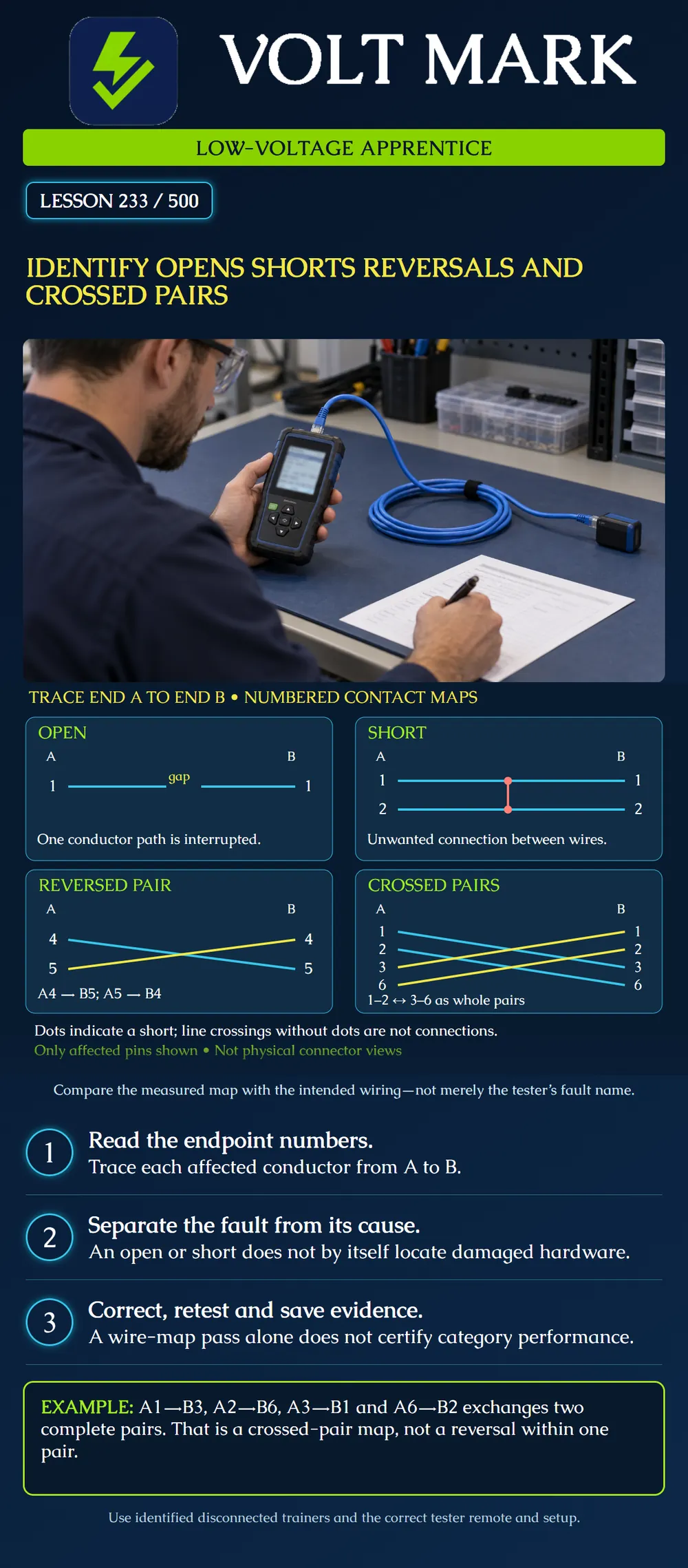
Read a numbered conductor map, classify four common wiring faults and distinguish the measured fault from an unconfirmed physical cause.
For the straight-through training link, corresponding contacts should connect: A1 to B1 through A8 to B8, while preserving physical pair membership. A and B identify the cable ends, not T568A and T568B wiring schemes. The poster shows only affected contacts. It is not a front or rear connector view. Follow actual product instructions for physical pin orientation.
An open is an interrupted conductor path. A short is an unintended connection between conductors. A reversed pair swaps the two conductors within one pair. Crossed pairs move complete pairs to different pair positions at the other end. Fluke distinguishes these from a split pair, where matching pin continuity can remain while the original physical pairs are separated. Wire mapping does not establish full bandwidth performance. [1]
OPEN: The A1-to-B1 line contains a gap. This represents loss of the intended electrical path, not a measured location or length. SHORT: Pins 1 and 2 have an unintended joining path. The red dots explicitly show electrical connections. REVERSED PAIR: A4 connects to B5 and A5 connects to B4. The conductors of the 4–5 pair are interchanged. CROSSED PAIRS: A1 connects to B3, A2 to B6, A3 to B1 and A6 to B2. The 1–2 and 3–6 pairs exchange positions. Their individual pair relationships are retained.
Crossing drawing lines without a dot are not electrical shorts. Trace the labels rather than classify a fault from the shape of the lines alone. Blue and yellow distinguish diagram paths; they are not conductor color assignments.
The instructor gives the learner a saved map. Before selecting a fault name, write every affected endpoint connection. Example record: Sample W-233-C A1 → B3 A2 → B6 A3 → B1 A6 → B2 Other contacts: verify from the full report Classification: whole-pair exchange Physical cause: not yet confirmed
The classification describes the measured map. It does not prove that the near-end jack, far-end plug or cable is the faulty component.
Follow the tester's supported setup and remote requirements. Fluke's MicroScanner2 guidance explains that a short can prevent the remote and unaffected wire mapping from appearing, and that some open-circuit details depend on the far-end termination. [2] Do not fill missing data with assumed good connections. Record “not displayed” or “not established by this test” when appropriate. Distance estimates and connector-end indications are diagnostic evidence, not permission to cut cable at an assumed exact location.
The learner sees an open and immediately plans to replace the far-end jack. First verify the cable ID, correct remote, adapter condition and test setup. Inspect the indicated accessible connections under the approved disconnected-work procedure. A missed contact, broken conductor, damaged connector or another problem may explain the observation. Record the confirmed cause, or leave it unconfirmed if the evidence is insufficient. Do not replace unrelated components simply because the display uses the word open.
A report identifies a short between two conductors but does not show the complete remaining map. The learner writes “all other wires good.” Correct the record. The missing map was not established. After the authorized repair, repeat the complete test and review every conductor. A fault can obscure additional faults.
In the reversal example, pair position 4–5 stays at 4–5, but its conductor order changes. In the crossed-pair example, the complete 1–2 pair arrives at 3–6 instead. An intentionally specified crossover assembly requires its own expected map. This poster classifies those connections as faults relative to the stated straight-through trainer. Do not use device link-up or automatic compensation as acceptance of a wiring map that conflicts with the work order.
Use only identified, disconnected training links for the exercise. Live service work needs authorization and an appropriate isolation procedure. Correct the documented defect under the connector instructions, repeat the required tests, and retain the initial fault, action and retest result. Record sample ID, endpoint IDs, expected map, tester/remote/setup, measured connections, fault classification, confirmed cause and report filenames. Keep inspection findings separate from instrument results.
What does A4→B5 and A5→B4 mean? Reversal within the 4–5 pair. Does a crossing line automatically mean short? No; follow endpoint labels and junction symbols. Does an open prove which jack failed? No. May undisplayed contacts be called good? No. Does a wire-map pass certify the full category performance? No.
Mistake: Classifying a crossing in the drawing as a short without tracing its labels. Correction: Write the endpoint map and inspect junction symbols; crossing lines alone do not establish an electrical connection.
Mistake: Calling undisplayed contacts good when a short obscures the remaining map. Correction: Record those paths as not established and repeat the complete mapping check after authorized correction.
Mistake: Replacing the far-end jack solely because the report says open. Correction: Verify the sample, remote and setup, then inspect supported diagnostic locations and record a confirmed physical finding.
How does A4 to B5 and A5 to B4 differ from exchanging 1-2 with 3-6?
Answer: The first reverses conductors within one pair position; the second moves whole pairs to different positions.
Why state the expected straight-through map first?
Answer: A connection is judged against the intended assembly; a deliberately specified crossover has a different expected map.
[1] Fluke Networks, Wire Map Testing: It’s Not All About Color. https://www.flukenetworks.com/blog/cabling-chronicles/wire-map-testing-it-s-not-all-about-color [2] Fluke Networks, Twisted Pair Test Results – MicroScanner2. https://www.flukenetworks.com/knowledge-base/microscanner2/twisted-pair-test-results-microscanner2 Instrument display behavior is model-specific.
Texas journeyman, 15 questions, scored by topic against the 70% mark. No card, and no account needed to start.
Free study material for low-voltage apprentices. This is a national foundation course: requirements differ by state and by local jurisdiction, and a practice that is common in one place is not a rule everywhere. Nothing here is a licence, a certification, or authority to work unsupervised, and completing it does not count as apprenticeship hours or continuing-education credit. Check the codes adopted where you are working, the licensing authority for that work, and your employer's safety programme. VoltMark is not affiliated with, endorsed by, or sponsored by NFPA, OSHA, NICET, BICSI, FOA, or any state or local licensing authority.

Electrician licensing exam prep: practice questions, timed exam simulations, and step-by-step help finding every answer in the NEC.