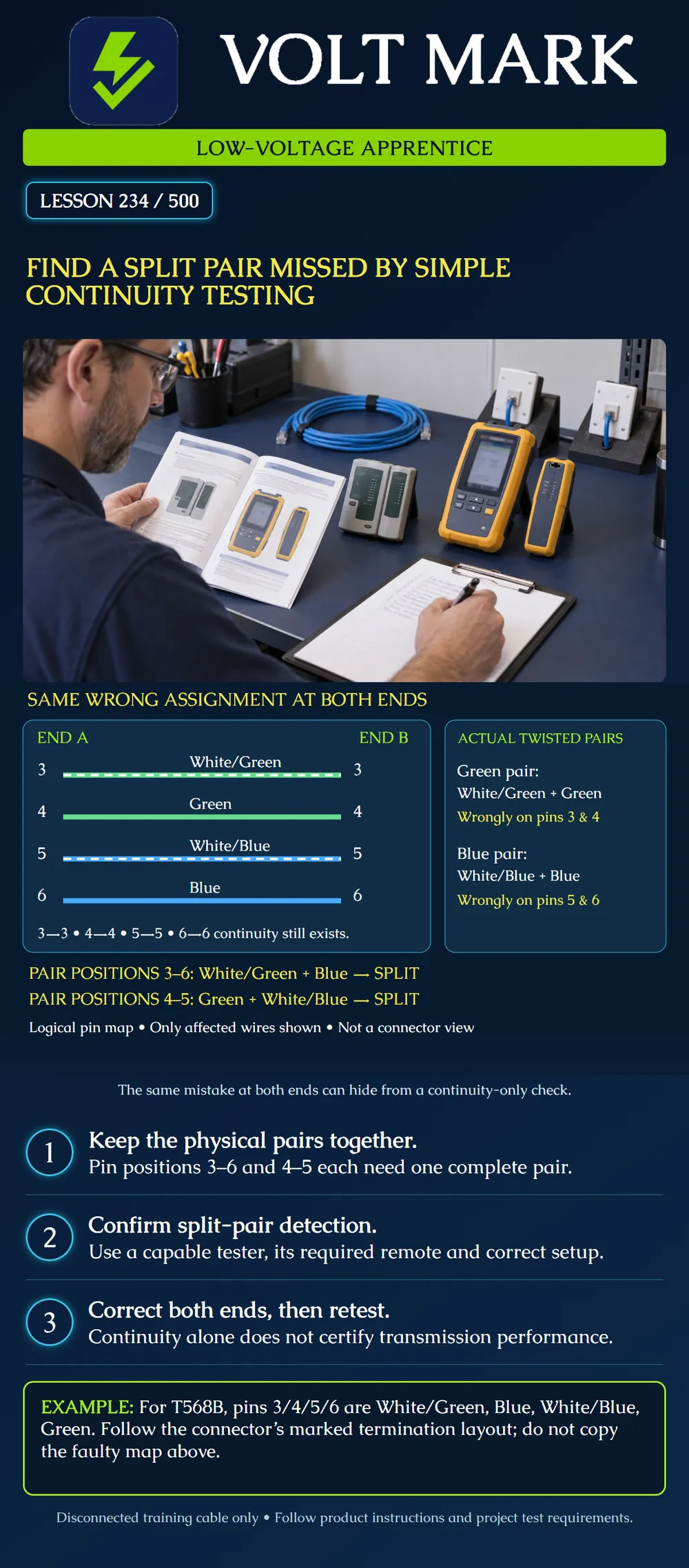
Explain why an apparently straight-through pin map may still contain a split pair. On a disconnected training sample, compare conductor identities with the specified wiring scheme and select a test method that can detect the fault.
A continuity-only check asks whether a conducting path reaches an endpoint. Pair integrity asks whether the two conductors assigned to a signal pair are the two that were twisted together in the cable. Those are different questions. Fluke describes a split pair as correct end-to-end continuity using conductors from different physical pairs, producing excessive crosstalk. A tester must have suitable split-pair detection; eight lights in order are not sufficient evidence by themselves.
This is a logical assignment table, not a plug-facing drawing or a jack punchdown layout. End A and End B are endpoint names. They do not mean T568A and T568B.
At BOTH ends of this deliberately faulty example: Pin 3: White/Green Pin 4: Green Pin 5: White/Blue Pin 6: Blue
Trace each conductor. Pin 3 reaches pin 3, pin 4 reaches pin 4, pin 5 reaches pin 5 and pin 6 reaches pin 6. However, the cable's actual green pair now occupies positions 3 and 4; the actual blue pair occupies positions 5 and 6. Required pair positions 3 and 6 therefore contain White/Green plus Blue. Required pair positions 4 and 5 contain Green plus White/Blue. Each combines conductors from different physical pairs.
The omitted pins 1, 2, 7 and 8 are not represented by a test result in this illustration. In an actual exercise, inspect and test all required conductors, not just those pictured.
For the T568B example in this lesson, positions 3, 4, 5 and 6 should contain White/Green, Blue, White/Blue and Green respectively. That keeps the green pair on 3–6 and the blue pair on 4–5. Use the actual connector's manufacturer labeling when terminating; rear IDC positions need not appear in numeric order. The project determines the accepted wiring scheme. This lesson does not impose one scheme across every U.S. jurisdiction.
In the crossed-pair example, whole pairs reached different numbered pair positions at the far end. Here the endpoint numbers match, but physical pair membership is wrong. Saying only “miswired” loses useful information. Record the observed map and the fault indication separately.
Use an identified, disconnected training cable with both ends available. Have the instructor provide a known-good sample and a deliberately faulty sample. Do not introduce a fault into operating building cabling.
Trainer ID: ______ Specified scheme: ______ Pin 3/4/5/6 colors at A: ______ Pin 3/4/5/6 colors at B: ______ Physical green-pair positions: ______ Physical blue-pair positions: ______ Continuity prediction: ______ Split-pair-capable method and remote: ______ Observed result: ______ Corrective work and final record: ______
Answer: 3 and 4.
Answer: It combines White/Green with Blue, which are from different physical pairs.
Answer: No. The conductor assignment must be corrected and verified.
Answer: No; required performance testing remains separate.
Mistake: Accepting eight matching pin numbers as proof that physical pairs are intact. Correction: Trace the cable's original twisted partners and use a method with documented split-pair capability.
Mistake: Repeating the same wrong color order at both ends to make continuity pass. Correction: Compare both ends with the selected scheme and connector labels, restoring physical pair membership as well as pin mapping.
Mistake: Calling the green conductors on positions 3 and 4 a valid 3-6 pair because the cable is green-coded. Correction: Trace positions explicitly: in this example 3-6 contains White/Green and Blue, so it combines different physical pairs.
Why can the illustrated fault have straight-through continuity?
Answer: Each wrong assignment is repeated at both ends, so each pin still reaches the same number even though pair partners are split.
Why check the tester's mode and sample-length limitations?
Answer: A capability claim only applies under the documented setup; a simple continuity mode may not test pair integrity.
Primary technical source, accessed September 30, 2026: Fluke Networks, Twisted Pair Test Results – MicroScanner2: https://www.flukenetworks.com/knowledge-base/microscanner2/twisted-pair-test-results-microscanner2 Supports split-pair definition, continuity/crosstalk distinction and model-specific wire-map examples. Its split-pair section repeats a sentence about crossed pairs; that sentence is not used here as a universal split-pair remote rule.
Texas journeyman, 15 questions, scored by topic against the 70% mark. No card, and no account needed to start.
Free study material for low-voltage apprentices. This is a national foundation course: requirements differ by state and by local jurisdiction, and a practice that is common in one place is not a rule everywhere. Nothing here is a licence, a certification, or authority to work unsupervised, and completing it does not count as apprenticeship hours or continuing-education credit. Check the codes adopted where you are working, the licensing authority for that work, and your employer's safety programme. VoltMark is not affiliated with, endorsed by, or sponsored by NFPA, OSHA, NICET, BICSI, FOA, or any state or local licensing authority.

Electrician licensing exam prep: practice questions, timed exam simulations, and step-by-step help finding every answer in the NEC.