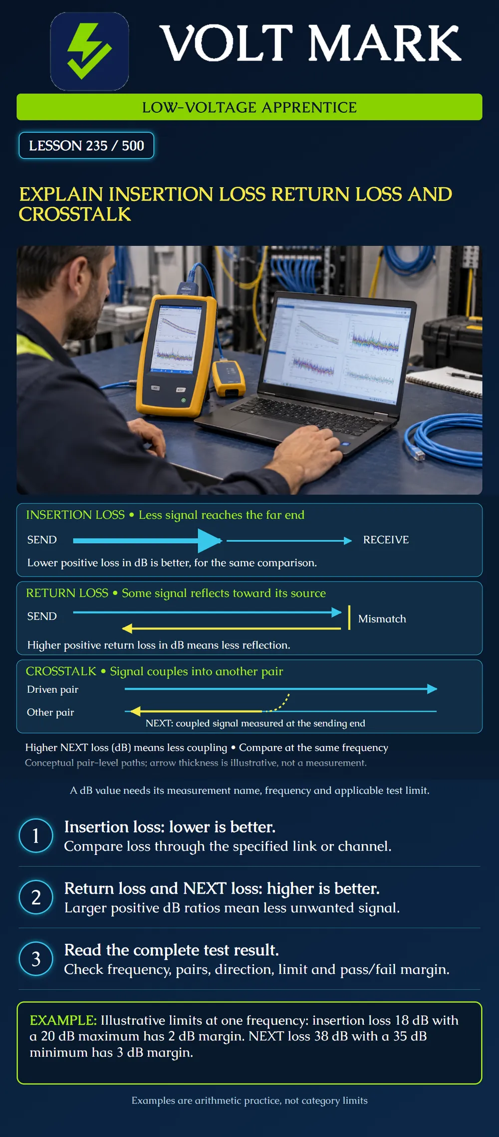
Describe three different transmission effects and interpret their measurement directions. Distinguish a measured value from its margin to a selected test limit.
Insertion loss describes reduction in transmitted signal through a link. With the positive loss convention used here, lower dB means less loss. The result depends on frequency, so one number without its frequency and test configuration is incomplete. Testing must cover the required range rather than a single convenient point. The forward arrows in the poster represent a conceptual reduction, not measured amplitudes.
An impedance discontinuity can reflect part of the signal back toward its source. Return loss compares incident power with reflected power. With RL = 10 log10(incident power / reflected power), a larger positive value means a smaller reflected fraction. “High return loss” is therefore favorable under this convention. Do not interpret it as a large amount of unwanted returned power. The poster's yellow backward arrow shows the reflected direction; the marked mismatch is a conceptual event, not a diagnosed connector.
A driven pair can couple unwanted signal into another pair. NEXT is near-end crosstalk, measured at the same end as the disturbing signal source. Higher NEXT loss in dB represents greater separation between the wanted source signal and coupled signal, hence less coupling. A NEXT failure alone does not prove a particular connector is responsible. Preserve designed pair geometry and use diagnostic evidence to investigate. The poster depicts whole-pair signal paths, not individual conductor connections; its dashed coupling arrow is not a physical short.
The first picture follows the desired signal to the other end. The second follows unwanted reflected energy back on the source path. The third follows unwanted energy into a different pair. These are distinct comparisons. Do not add the three displayed dB measurements to produce a “total cable score.” Their reference quantities differ.
These invented limits are NOT requirements from TIA, ISO or a cable category. Assume one frequency, the same stated configuration, and no special evaluation exclusions:
A lower insertion-loss measurement helps A, while higher NEXT and return-loss measurements help B and C. In each case a larger positive margin is favorable, but only relative to its own applicable limit. Raw measurements and margins are not interchangeable.
Using the positive return-loss convention: If reflected power is 1/100 of incident power, RL = 10 log10(100) = 20 dB. If reflected power is 1/1000 of incident power, RL = 10 log10(1000) = 30 dB. The 30 dB example has less reflected power. These are normalized teaching examples, not a test fixture specification or acceptance threshold.
An instructor supplies two saved reports for the same intended cabling configuration. Before comparing their largest numbers, write down:
If these fields are missing, label the comparison incomplete. Do not change the limit to make an existing failure disappear. Investigate whether the setup matches the actual project and retain the original evidence. Actual certification procedures, adapters, calibration and applicable exceptions belong to the tester instructions and specified acceptance method.
Report X lists NEXT “3 dB margin.” Report Y lists NEXT “38 dB measured.” A student says Y is much better. Explain the problem.
Answer: One number is distance from a limit; the other is the measured ratio. Without the applicable limits, frequency, pairs and configuration, that ranking is unsupported.
Answer: Insertion loss.
Answer: Back toward the source.
Answer: No; it means less coupling relative to the disturbing signal.
Answer: No. Use the specified test limit and frequency-dependent evaluation.
Answer: No.
Mistake: Treating larger positive return loss as more unwanted reflected power. Correction: Use the stated incident-to-reflected power ratio: 30 dB represents less reflection than 20 dB under this convention.
Mistake: Ranking 38 dB measured NEXT above a 3 dB NEXT margin without reading the limit. Correction: Identify whether each value is a measurement or margin and compare matching frequencies, pair combinations, boundaries and limits.
Mistake: Subtracting the limit from every measurement to calculate margin. Correction: For the supplied insertion-loss maximum use limit minus measurement; for the supplied NEXT and return-loss minima use measurement minus limit.
Fluke Networks, Attenuation (Insertion Loss) Measurement and Testing – DTX CableAnalyzer: https://www.flukenetworks.com/knowledge-base/dtx-cableanalyzer/attenuation-insertion-loss-measurement-and-testing-dtx Supports the insertion-loss concept and frequency-dependent testing.
Fluke Networks, What Is Return Loss?: https://www.flukenetworks.com/blog/cabling-chronicles/return-loss Supports incident/reflected power comparison and positive return-loss convention.
Fluke Networks, NEXT (Near-End Crosstalk) Troubleshooting: https://www.flukenetworks.com/knowledge-base/dtx-cableanalyzertm/next-near-end-crosstalk-troubleshooting Supports coupling, higher NEXT loss being favorable, and end/frequency-dependent evaluation. Historical category range and dated standards in that page are not adopted as universal current limits here.
Texas journeyman, 15 questions, scored by topic against the 70% mark. No card, and no account needed to start.
Free study material for low-voltage apprentices. This is a national foundation course: requirements differ by state and by local jurisdiction, and a practice that is common in one place is not a rule everywhere. Nothing here is a licence, a certification, or authority to work unsupervised, and completing it does not count as apprenticeship hours or continuing-education credit. Check the codes adopted where you are working, the licensing authority for that work, and your employer's safety programme. VoltMark is not affiliated with, endorsed by, or sponsored by NFPA, OSHA, NICET, BICSI, FOA, or any state or local licensing authority.

Electrician licensing exam prep: practice questions, timed exam simulations, and step-by-step help finding every answer in the NEC.