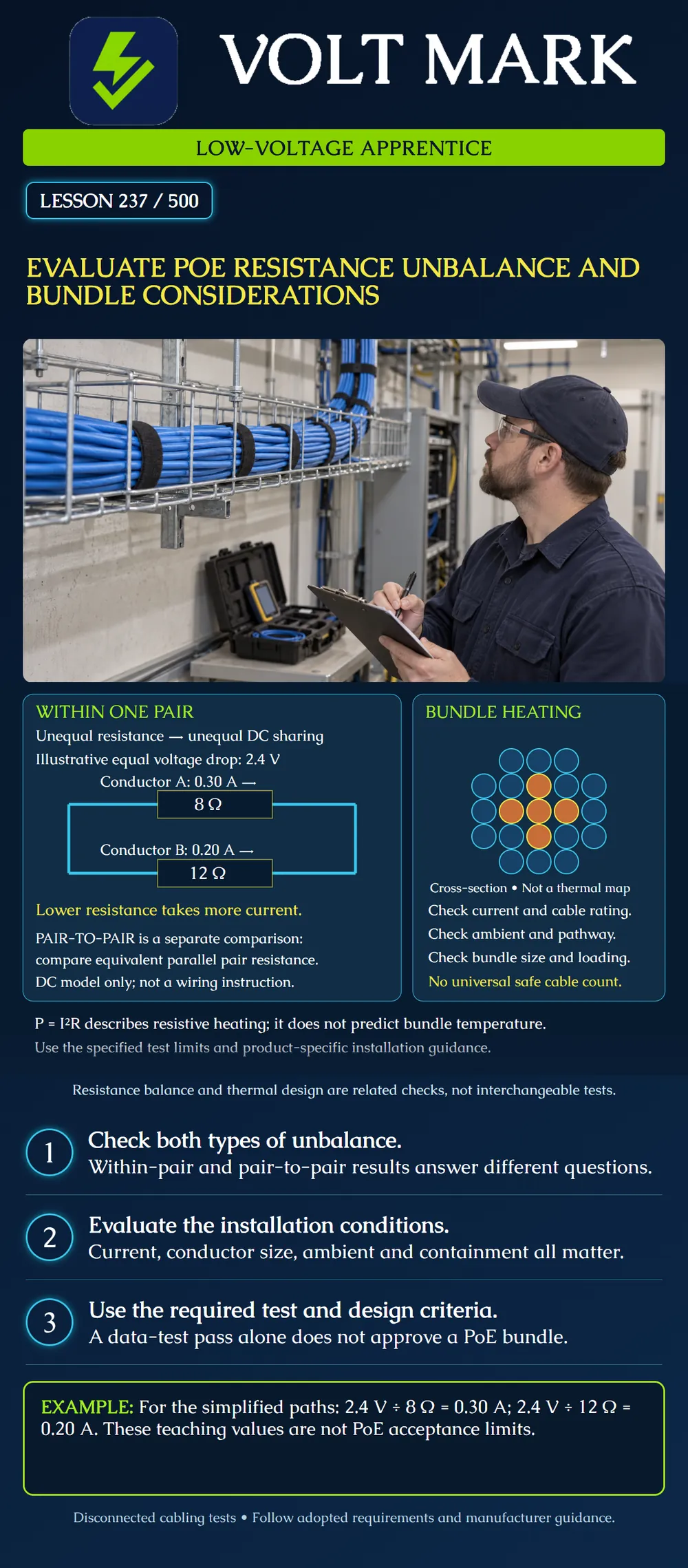
Distinguish resistance unbalance within one pair from unbalance between pairs, explain unequal current sharing, and identify the information needed before evaluating a powered cable bundle.
Within-pair unbalance compares the DC resistance of the two conductors belonging to one twisted pair. Pair-to-pair unbalance compares effective pair resistances. For PoE DC analysis the two conductors in a pair act as parallel paths; the effective resistance is not simply the sum used for a loop-resistance result. Use the instrument's defined parameter and applicable limit, rather than treating similarly named readings as interchangeable.
Fluke explains that excessive unbalance can interfere with simultaneous power and data operation. The test report must identify the actual unbalance measurements. A generic PASS does not establish that all requested PoE-related parameters were measured.
The drawing is a simplified DC sharing model, not an Ethernet pinout or a complete PSE/PD circuit. The source, return path, magnetics and negotiation circuitry are intentionally absent. Do not build this as a PoE wiring arrangement.
For this mathematical example alone, the two paths have the same 2.4 V longitudinal voltage drop: Conductor A: 8 ohms. Conductor B: 12 ohms. I_A = 2.4 / 8 = 0.30 A. I_B = 2.4 / 12 = 0.20 A. Total = 0.50 A. The current is unequal even though the paths experience equal voltage drop. The 2.4 V figure is not a PoE source voltage or an allowed cable drop.
The effective resistance of those parallel paths is: R_eq = (8 x 12) / (8 + 12) = 96 / 20 = 4.8 ohms. This is different from their 20-ohm series sum. Do not use this intentionally exaggerated example to select an unbalance pass/fail threshold. Percentage definitions and absolute-resistance provisions must come from the selected test method.
For a resistive path, P = I²R. In the example: P_A = 0.30² x 8 = 0.72 W. P_B = 0.20² x 12 = 0.48 W. Total resistive power = 1.20 W. Check: 2.4 V x 0.50 A = 1.20 W.
These values describe the invented parallel segment only. They do not predict a real cable's temperature rise. At fixed current, doubling resistance doubles I²R heating; at fixed voltage, current changes. Always state what is held constant before comparing heating scenarios.
Heat removal depends on installation conditions. Cable construction, conductor size, ambient temperature, loading and pathway type influence the thermal situation. Bundling can restrict heat dissipation. Temperature can also affect transmission performance, so an ampacity or temperature check does not replace the required data-performance assessment.
The colored center of the poster bundle is illustrative, not a measured thermal image. Its circle count is not a permitted bundle size. Product-specific tables have assumptions; do not extract a cable count while discarding cable type, ambient, PoE loading or containment conditions.
A work order proposes adding powered access points to an existing cable route. The file contains a data certification report but no remote-power design record. Before approving the change, assemble:
This worksheet identifies missing evidence; it does not authorize an apprentice to approve a thermal design. Escalate unresolved design or acceptance questions to the responsible qualified person.
For disconnected cabling, select the supported tester method and adapters from Lesson 236. Confirm that the configured test actually includes the requested unbalance parameters. Retain the exact limit and full results. If a reading fails, inspect the documented setup and use diagnostic evidence before deciding whether a termination, component or cable needs correction. Follow authorized procedures and retest after corrective work.
Answer: No.
Answer: The 8-ohm path carries 0.30 A.
Answer: No; thermal conditions are missing.
Answer: No.
Answer: No; operating behavior does not replace the specified evidence.
Mistake: Reporting the 20-ohm series sum as the effective resistance of the two parallel model paths. Correction: Identify the measurement being compared; for this parallel model use (8 x 12)/(8 + 12) = 4.8 ohms, keeping loop resistance separate.
Mistake: Converting the model's 1.20 W into a claimed cable temperature rise. Correction: Record it only as the invented segment's resistive power and obtain the actual thermal conditions and design assessment before drawing temperature conclusions.
Mistake: Approving added powered access points from a generic data PASS report. Correction: Check whether the required unbalance results are included and collect the cable, loading, ambient and pathway information for the responsible design reviewer.
Fluke Networks, DC Resistance Unbalance: What You Need to Know (2025): https://www.flukenetworks.com/blog/cabling-chronicles/dc-resistance-unbalance-what-you-need-know Supports within-pair versus pair-to-pair comparisons, parallel pair resistance and PoE/data implications. Its numeric thresholds and field-test requirement discussion are not used here as universal current rules.
Siemon, Bundling Recommendations for PoE and POH Applications (2016): https://www.siemon.com/en/bundling-recommendations-for-poe-and-poh-applications/ Supports cable-construction, pathway and temperature/performance considerations. Product-specific guidance must be checked for the actual installation; historical broad safety statements are not generalized.
This lesson gives no universal bundle count, ampacity or NEC article number. Requirements depend on the applicable adopted edition and installation.
Texas journeyman, 15 questions, scored by topic against the 70% mark. No card, and no account needed to start.
Free study material for low-voltage apprentices. This is a national foundation course: requirements differ by state and by local jurisdiction, and a practice that is common in one place is not a rule everywhere. Nothing here is a licence, a certification, or authority to work unsupervised, and completing it does not count as apprenticeship hours or continuing-education credit. Check the codes adopted where you are working, the licensing authority for that work, and your employer's safety programme. VoltMark is not affiliated with, endorsed by, or sponsored by NFPA, OSHA, NICET, BICSI, FOA, or any state or local licensing authority.

Electrician licensing exam prep: practice questions, timed exam simulations, and step-by-step help finding every answer in the NEC.