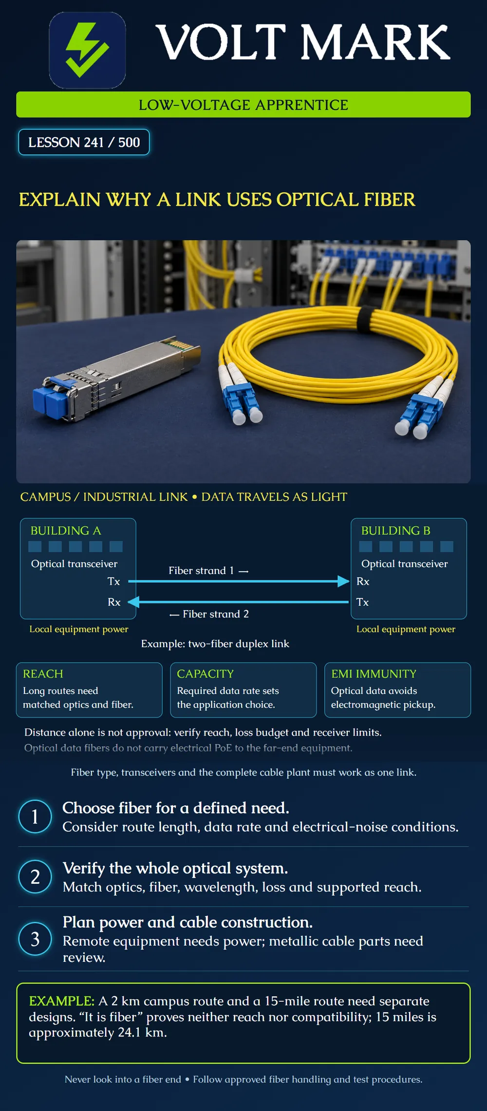
Explain why an optical link may suit a campus or industrial application, then identify the information needed before claiming that a particular link will work.
A transmitter converts an electrical data signal into modulated light. The cable plant carries that light to a receiver, which converts it back into an electrical signal. The poster shows a common two-fiber duplex arrangement: Building A transmit reaches Building B receive on one strand, and Building B transmit reaches Building A receive on the other. It is a functional diagram, not a connector polarity drawing.
Other designs exist, including bidirectional systems that share one strand using appropriate optics. Do not infer the number of required fibers solely from the word “fiber.” The selected application and equipment define the arrangement.
Why choose fiber? Distance: optical systems can serve routes beyond the reach of many balanced-pair Ethernet applications when the fiber and transceivers are correctly selected. Capacity: fiber supports high data rates, but the actual application, optics and cable-plant specifications set performance. Electrical noise: the optical signal in the glass is immune to electromagnetic interference. This is useful around industrial machinery and on routes where electrical noise makes a conductive data path undesirable.
These benefits are design reasons, not a promise of unlimited distance or speed. A connector fitting an optical module does not establish compatibility.
Scenario A: a campus network needs a 2 km route between buildings. Scenario B: a remote industrial facility needs a 15-mile route.
Convert Scenario B: 15 x 1.609344 = 24.14016 km, approximately 24.1 km. That conversion describes route scale only. It does not select a transceiver or establish a passing loss budget.
For each scenario, identify the required data rate, actual cable route length including allowances, available fiber type, endpoint interfaces, operating environment, and expected connectors/splices. Then obtain the supported optical specifications. Do not extend a module beyond its stated application reach merely because a simple power calculation appears favorable.
What still limits the link? The transmitter and receiver must support the application and intended fiber. Wavelength, fiber type, optical loss, dispersion/bandwidth and receiver input limits matter. The cable plant must fit the supported link requirements with the design margin required by the project. A receiver can have both a minimum usable input and a maximum acceptable input; more received optical power is not always better.
A loss budget is a planned allowance for the cable plant. Installed measurements later verify relevant performance; planning alone does not prove the installed result. Later fiber lessons develop these concepts and tests in detail.
The two optical strands in the poster carry communication signals, not electrical PoE. Each building's equipment has a separately planned power source. A fiber-fed media converter or switch may provide PoE on a local copper connection when appropriately powered and specified. That does not mean the glass itself carried electrical PoE across campus.
Hybrid/composite cables can contain both fibers and electrical conductors. Their power conductors, supplies, connectors and installation requirements are separate design considerations. Do not confuse an optical data path with a complete remote-power solution.
Glass fiber is dielectric, but a cable may include metallic armor or other conductive elements. Electrical isolation and bonding decisions must account for the actual cable and hardware. Follow the product instructions and applicable adopted installation requirements. “Fiber” is not a universal exemption from electrical-safety or building-entry obligations.
The scope here is low-voltage communications. Utility power-line construction or work on energized equipment is not part of this apprentice exercise.
For each scenario, complete: Purpose and required data rate: ______ Endpoint locations and actual route: ______ Fiber type and strand arrangement: ______ Supported optics/application reach: ______ Wavelength and connector compatibility: ______ Cable-plant loss allowance and margin: ______ Receiver input constraints: ______ Far-end equipment power source: ______ Cable construction and environment: ______ Required inspection/testing records: ______ Unresolved design questions: ______
If a critical field is unknown, call the design incomplete rather than guessing. A useful apprentice explanation states both the reason for choosing fiber and the evidence still needed.
Answer: Building B receive.
Answer: No; approximately 24.1 km.
Answer: No.
Answer: No.
Answer: No; the application, fiber, optics and cable-plant constraints must also match.
A fictional proposal for the 15-mile route lists only single-mode cable and modules described as 10 km optics. It has no detailed supported-link specifications or far-end power plan. Explain why the proposed design is incomplete without selecting equipment. Suggested answer: 15 miles is about 24.1 km, so the described module reach does not support that route as proposed. Obtain the exact application and optical specifications, actual cable-plant details, loss and dispersion constraints, receiver limits and planned equipment power. A favorable power estimate alone would not authorize exceeding the supported application reach.
Mistake: Reading the 15-mile route as 15 km when comparing optical-module reach. Correction: Convert it to approximately 24.1 km, then verify the actual routed cable length and supported application specifications.
Mistake: Assuming fiber to Building B supplies electrical PoE to its equipment. Correction: Document the far-end power source and any local copper PoE equipment separately from the optical data path.
Mistake: Treating optical EMI immunity as proof that the whole cable has no conductive elements. Correction: Check the actual armor, strength members and hardware before referring isolation and bonding questions to the responsible designer.
Corning, Optical Fiber Advantage: https://www.corning.com/optical-communications/worldwide/en/home/products/fiber/optical-fiber-advantage.html Supports optical transmission and EMI/capacity benefits.
Fiber Optic Association, Fiber Optic Data Links: https://thefoa.org/tech/ref/appln/datalink.html Supports transceiver/cable-plant matching, rate, length, bandwidth and loss constraints.
Fiber Optic Association, Outside Plant Fiber Optic Cables: https://www.thefoa.org/tech/ref/OSP/cable.html Supports identifying metallic elements and associated grounding/bonding considerations.
Corning, Distance and Wattage Considerations Drive Power Decisions: https://www.corning.com/in-building-networks/worldwide/en/home/applications/local-area-networks/knowledge-center/traditional-lan-knowledge-center/distance-wattage-considerations-drive-power-decisions.html Supports distinct power planning and composite fiber/copper arrangements.
Texas journeyman, 15 questions, scored by topic against the 70% mark. No card, and no account needed to start.
Free study material for low-voltage apprentices. This is a national foundation course: requirements differ by state and by local jurisdiction, and a practice that is common in one place is not a rule everywhere. Nothing here is a licence, a certification, or authority to work unsupervised, and completing it does not count as apprenticeship hours or continuing-education credit. Check the codes adopted where you are working, the licensing authority for that work, and your employer's safety programme. VoltMark is not affiliated with, endorsed by, or sponsored by NFPA, OSHA, NICET, BICSI, FOA, or any state or local licensing authority.

Electrician licensing exam prep: practice questions, timed exam simulations, and step-by-step help finding every answer in the NEC.