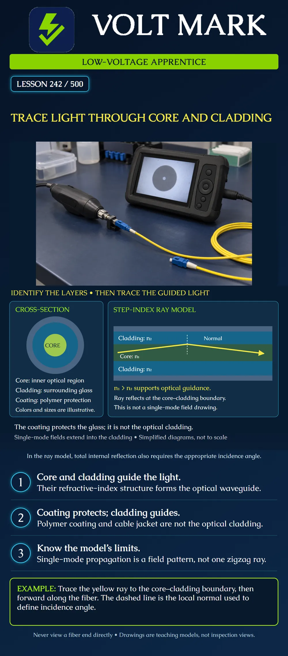
Identify the optical core and cladding, distinguish them from protective layers, and explain the simplified ray model without confusing it with a full description of single-mode propagation.
The poster's center region is the core. The surrounding blue glass region is the cladding. The outer gray-blue layer represents polymer coating. The colors and dimensions are teaching choices, not standard identification colors or a scale drawing. Buffers, strength members and the outer cable jacket are not shown.
The core and cladding together form an optical waveguide. In the conventional step-index model shown, the core has refractive index n1 and the cladding has a lower refractive index n2. The coating protects the glass during handling and service; it is not a substitute for the cladding's optical function.
The yellow line represents a simplified ray traveling forward through a step-index core. It meets the upper core–cladding interface and changes direction while continuing forward. The dashed vertical line marks the local normal: a line perpendicular to that interface.
For a ray traveling from higher index to lower index, total internal reflection occurs when the incidence angle, measured FROM THE NORMAL, exceeds the critical angle. Measuring from the fiber axis or boundary gives a complementary angle; never mix those angle conventions. The poster does not assign a numerical angle or numeric refractive indices.
Both the material-index relationship and the angle matter. A claim that every ray entering any fiber is automatically trapped is incorrect. Coupling conditions at the fiber entrance are a separate part of understanding how light enters the guided structure.
Refractive index describes how light propagates in a material relative to vacuum. The symbols n1 and n2 are material optical properties, not electrical voltage levels or conductor numbers. A change in refractive index need not be a visible reflective coating. The cladding is not a metal mirror wrapped around the core.
The step-index ray model helps explain guidance, but it is not a universal drawing of all fibers. Graded-index multimode fiber has an index that changes across the core, so its ray picture differs. Single-mode fiber is best understood through its guided electromagnetic field. That field extends into the cladding; it is not a tiny bright line perfectly confined to a geometric core.
Mode field diameter describes the optical field distribution and is not simply another name for physical core diameter. Later lessons compare fiber types and explain why these distinctions matter when matching fibers, connectors and splices.
The instructor provides a diagram with three unlabeled nested regions: A: central optical region. B: glass surrounding A. C: polymer outside B.
Label A core, B cladding and C coating. Explain why removing C for an authorized termination process does not mean the worker intentionally removed B. This is a diagram exercise, not permission to strip or cleave fiber. Hands-on preparation requires the appropriate training, tools, product instructions and fiber-fragment controls.
Draw one forward ray inside a rectangular step-index core. At its encounter with the boundary:
If the drawing shows the ray reflecting off the outer polymer layer, correct it. If it calls the ray a literal single-mode path, correct that statement too.
Identify the physical layer being discussed before following a preparation or inspection instruction. A cable jacket, buffer/coating and glass cladding are different things. Do not use this conceptual drawing to infer strip lengths, bend limits or allowed surface damage.
Optical guidance also does not eliminate attenuation or make damaged fiber acceptable. Actual link performance depends on the selected fiber and components, installation quality and required testing. Never look into an exposed fiber to decide whether it is carrying light; operating wavelengths may be invisible.
Answer: Cladding.
Answer: The core index n1.
Answer: The normal used to define incidence angle.
Answer: No.
Answer: No; it extends into the cladding.
Answer: No.
A learner labels a sketch's central region core, the surrounding glass coating and the outer polymer cladding. The yellow ray is drawn reflecting at the polymer boundary. Correct the second label to cladding and the third to coating; in the stated step-index ray model, place the guidance interface between core and cladding. Draw the local normal perpendicular to that interface and describe incidence angle from the normal. Keep the drawing identified as a simplified ray model rather than a literal single-mode field path. Correct labels alone do not establish a real fiber's condition or performance.
Mistake: Calling polymer coating the cladding because both surround the core. Correction: Identify the surrounding glass as optical cladding and the outer polymer as protection before interpreting preparation instructions.
Mistake: Comparing an angle drawn from the fiber axis with a critical angle defined from the normal. Correction: Mark the interface and its perpendicular normal, then state and use one consistent angle convention.
Mistake: Treating the yellow ray as a literal single-mode path wholly inside the core. Correction: Label it as a simplified step-index ray illustration and distinguish the guided field, which extends into the cladding.
Fiber Optic Association, Total Internal Reflection in Optical Fiber: https://www.thefoa.org/tech/ref/basic/total_internal_reflection.html Supports the layered structure and step-index guidance explanation. Angle wording in introductory sources may use the axis/interface reference; this lesson explicitly uses the normal for incidence angle and does not reproduce the source's acceptance-cone arithmetic.
Corning, Optical Fiber Glossary of Terms: https://www.corning.com/optical-communications/in/en/home/products/fiber/optical-fiber-resource-center/glossary-of-terms.html Supports core/cladding roles, refractive-index relationship and mode-field distribution into the cladding.
Texas journeyman, 15 questions, scored by topic against the 70% mark. No card, and no account needed to start.
Free study material for low-voltage apprentices. This is a national foundation course: requirements differ by state and by local jurisdiction, and a practice that is common in one place is not a rule everywhere. Nothing here is a licence, a certification, or authority to work unsupervised, and completing it does not count as apprenticeship hours or continuing-education credit. Check the codes adopted where you are working, the licensing authority for that work, and your employer's safety programme. VoltMark is not affiliated with, endorsed by, or sponsored by NFPA, OSHA, NICET, BICSI, FOA, or any state or local licensing authority.

Electrician licensing exam prep: practice questions, timed exam simulations, and step-by-step help finding every answer in the NEC.