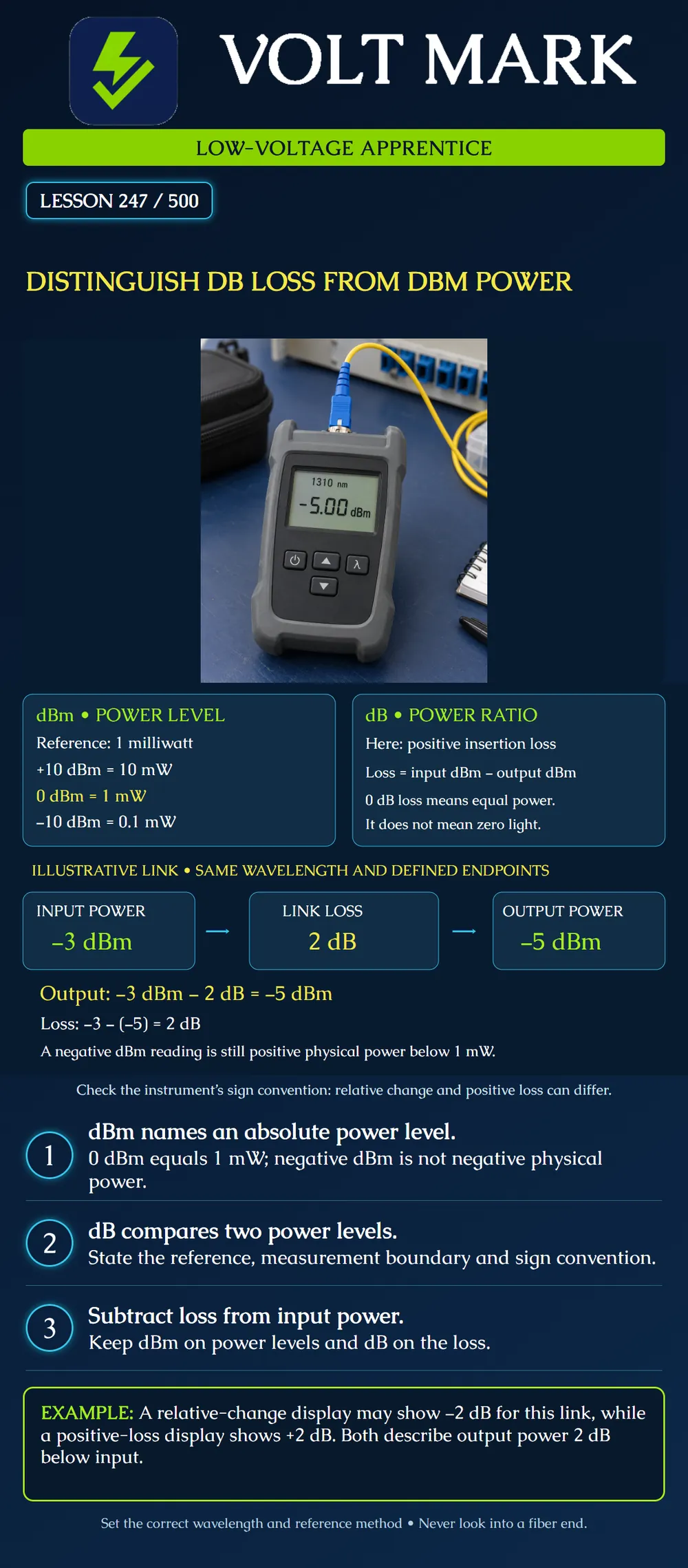
Interpret an optical power reading in dBm, calculate a positive insertion loss in dB, and identify the sign convention before interpreting an instrument result.
dBm expresses a power level relative to the fixed reference of 1 milliwatt. dB expresses a logarithmic ratio between powers. A dB result needs its reference and context; it is not an absolute optical power level by itself.
The reference anchors are: +10 dBm = 10 mW. 0 dBm = 1 mW. -10 dBm = 0.1 mW.
A negative dBm value means less than 1 mW, not a negative amount of physical power. Zero dBm is not zero light. Similarly, zero dB loss means equal compared powers, not an unpowered link.
Assume a defined input and output boundary, the same wavelength and a valid comparison method: Input power: -3 dBm. Positive insertion loss: 2 dB. Output power = -3 dBm - 2 dB = -5 dBm.
Work backwards: Loss = input power level - output power level. Loss = -3 - (-5) = +2 dB.
These are invented teaching values, not acceptable limits for a receiver. Whether -5 dBm is appropriate depends on the actual receiver's specified input range and the application.
Positive insertion loss uses L = 10 log10(P_in / P_out). Relative change uses delta = 10 log10(P_out / P_ref).
If the input is the reference in the lesson example, relative change is -2 dB and positive loss is +2 dB. These do not describe different amounts of loss; the ratio is expressed in opposite directions. Read the instrument's mode and instructions before interpreting the sign. Do not change a sign just to make a result look favorable.
P_mW = 10^(P_dBm / 10). At -3 dBm: approximately 0.5012 mW. At -5 dBm: approximately 0.3162 mW. Output/input = approximately 0.6310. Thus about 63.1 percent of the input power remains in this model. A 2 dB loss is not a 2 percent loss.
The familiar “3 dB is half power” rule is approximate: exact half power corresponds to about 3.0103 dB loss. Use the precision required by the calculation, not more digits than the measurement supports.
For a simple passive path at one wavelength, appropriately defined successive positive losses in dB can be added. For example, 1.2 dB plus 0.8 dB is 2.0 dB. Subtract that loss from the input dBm level to obtain the modeled output.
Do not add two dBm power readings arithmetically to obtain their total physical power. Combining powers, when physically and technically appropriate, requires conversion to linear units and a valid system model. A dBm reading is a logarithmic level, not a number of milliwatts.
Before interpreting a saved result, identify: Instrument and selected mode: ______ Measurement wavelength: ______ Absolute power or relative measurement: ______ Reference value/method if applicable: ______ Input and output boundaries: ______ Sign convention: ______ Units beside every recorded value: ______ Applicable receiver or loss criterion: ______
A meter's wavelength selection applies its measurement calibration; it does not magically convert the transmitted wavelength. Follow the source/meter instructions and the approved reference procedure. This lesson teaches reading and arithmetic, not a substitute for that procedure.
A worksheet says “receiver = -5” and “loss = 2” with no units or reference. The numbers resemble the poster example but are incomplete evidence. Recover the original measurement record. Do not infer that the first is dBm or the second positive dB merely because the arithmetic could work.
Answer: 1 mW.
Answer: No; it is 0.1 mW.
Answer: -5 dBm.
Answer: 2 dB.
Answer: No; check the ratio convention.
Answer: No.
For a fictional passive path with the same wavelength and defined boundaries, input power is -4 dBm and positive insertion loss is 3 dB. Calculate output power, the output-relative-to-input change in dB and the approximate fraction of input power remaining. State whether a missing receiver specification allows acceptance. Do not make a measurement.
Answer: Output is -4 - 3 = -7 dBm. Relative change is -7 - (-4) = -3 dB, while positive loss is +3 dB. The remaining power fraction is 10^(-3/10), about 0.501, or 50.1 percent. None of these values establishes receiver acceptance without its applicable operating limits and the other link requirements.
Mistake: Recording 0 dBm as no light and a negative dBm reading as invalid. Correction: Use the fixed 1 mW reference: 0 dBm is 1 mW, and negative dBm represents positive power below that reference.
Mistake: Adding two dBm readings to calculate combined physical power. Correction: Convert to linear power only when the system model permits combining those powers; do not treat logarithmic levels as milliwatts.
Mistake: Flagging -2 dB relative change and +2 dB insertion loss as contradictory. Correction: Identify each ratio's direction and reference; the lesson's two signs describe the same input/output comparison under different conventions.
Fluke Networks, dB vs dBm: https://www.flukenetworks.com/knowledge-base/dsp-fta-series/db-vs-dbm Supports dBm referenced to 1 mW and positive optical-loss subtraction.
Fiber Optic Association, Measuring Power in dB and dBm: https://www.thefoa.org/tech/ref/testing/test/dB.html Supports logarithmic power units, reference measurements and differing instrument sign conventions. This lesson uses neutral sign definitions rather than adopting the source's editorial commentary.
Texas journeyman, 15 questions, scored by topic against the 70% mark. No card, and no account needed to start.
Free study material for low-voltage apprentices. This is a national foundation course: requirements differ by state and by local jurisdiction, and a practice that is common in one place is not a rule everywhere. Nothing here is a licence, a certification, or authority to work unsupervised, and completing it does not count as apprenticeship hours or continuing-education credit. Check the codes adopted where you are working, the licensing authority for that work, and your employer's safety programme. VoltMark is not affiliated with, endorsed by, or sponsored by NFPA, OSHA, NICET, BICSI, FOA, or any state or local licensing authority.

Electrician licensing exam prep: practice questions, timed exam simulations, and step-by-step help finding every answer in the NEC.