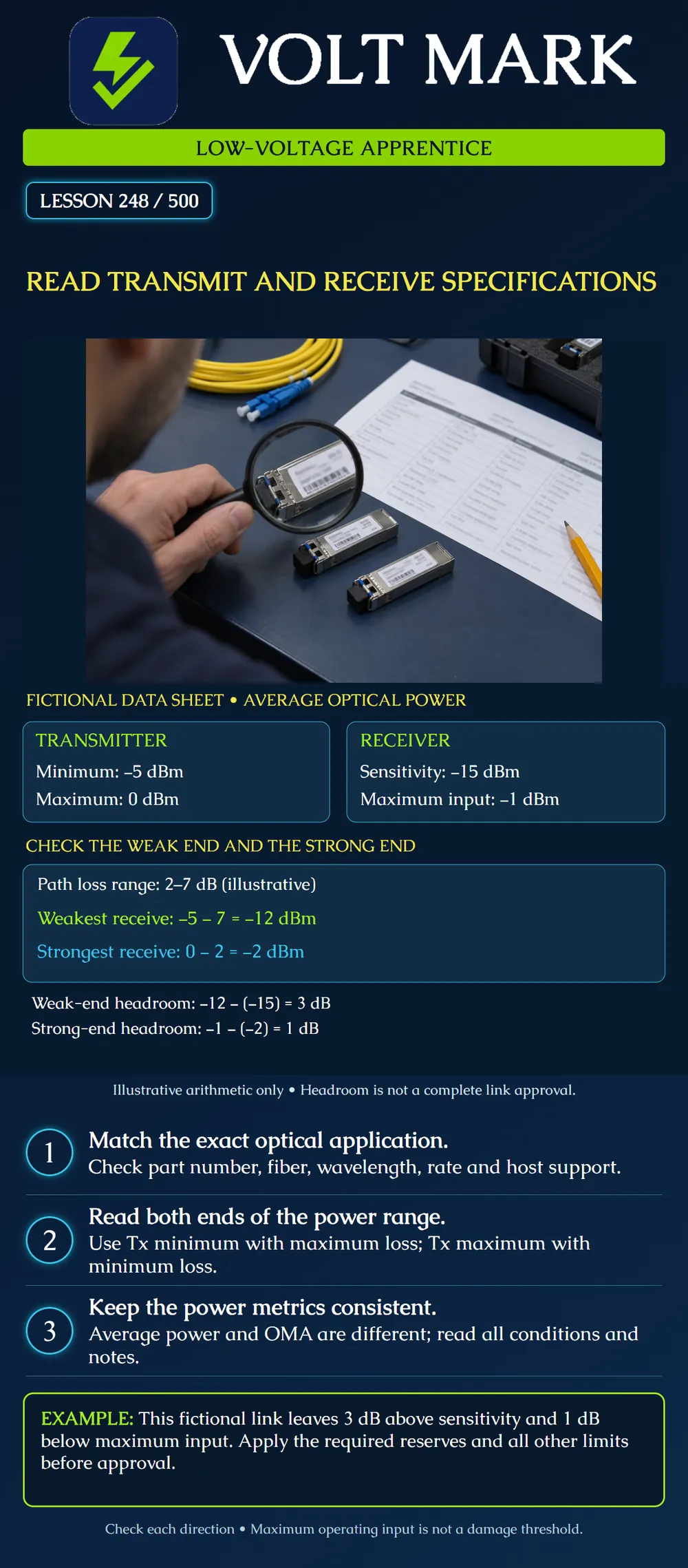
Read the optical specifications for a proposed pair of transceivers, identify the correct power metric, and check both the weakest and strongest predicted received signals. This is a document-reading and arithmetic exercise; it does not certify a real link.
Start with the exact module part number, revision and supported host. Record the intended application, data rate, fiber type, connector, transmit wavelength and receive wavelength range. For a bidirectional single-fiber pair, check the complementary wavelengths rather than assuming identical transmit wavelengths at both ends. Retain the manufacturer's conditions, not just a copied number from a distributor.
In Cisco's cited data sheet, Table 4 lists SFP-10G-LR transmit power from −8.2 to +0.5 dBm and receive power from −14.4 to +0.5 dBm. Its footnote says these are average-power specifications unless otherwise identified. The LRM row separately specifies average and optical modulation amplitude (OMA), and requires both. These product examples illustrate how to read a table; they are not the fictional values in our poster. Cisco also distinguishes receiver overload from damage threshold in its ZR specifications. Do not substitute a damage threshold for the maximum operating input.
A receiver needs enough signal to meet its specified performance under the stated test conditions. Excessive signal can overload it. A power reading within that interval alone does not prove the complete link meets its application. Fiber bandwidth, dispersion, reflectance, compatibility and other specified requirements still matter.
Use guaranteed limits and their conditions. A typical value describes a typical case; it does not automatically replace a guaranteed minimum or maximum. Retain the temperature range, wavelength, application mode and any error-rate or correction conditions beside the value.
The following numbers were created for this lesson and are not a manufacturer's product specification.
Transmitter minimum average optical power: −5 dBm. Transmitter maximum average optical power: 0 dBm. Receiver sensitivity, using the same average-power basis: −15 dBm. Receiver maximum operating input: −1 dBm. Predicted end-to-end passive path loss range: 2 to 7 dB. These classroom endpoints exclude additional design reserves unless explicitly stated.
First calculate the weak case. Combine the lowest transmit power with the greatest loss: −5 dBm − 7 dB = −12 dBm. The difference above sensitivity is: −12 − (−15) = 3 dB.
Then calculate the strong case. Combine the highest transmit power with the smallest loss: 0 dBm − 2 dB = −2 dBm. The distance below the maximum operating input is: −1 − (−2) = 1 dB.
Both classroom endpoints fall inside the stated interval. Say exactly that. Do not write “approved” or “will work” on the strength of these two subtractions. Required reserves, uncertainty and the remaining specifications have not been evaluated. Check the reverse direction independently using its transmitter, receiver and path.
Change only the fictional minimum loss to 0.5 dB. The strongest received level becomes 0 − 0.5 = −0.5 dBm. That is 0.5 dB above the allowed −1 dBm maximum input. A shorter or lower-loss path is therefore not automatically acceptable.
Escalate the design discrepancy. If an approved design calls for attenuation, its loss tolerance and wavelength behavior must be included in both endpoints. Adding attenuation reduces the strong signal, but also reduces the weak signal. Do not install an arbitrary attenuator solely because a training example mentions one.
Use an instructor-supplied manufacturer sheet and a proposed link schedule. Work on paper; do not disconnect operating campus, industrial, security or life-safety circuits.
Use the fictional transmitter and receiver limits in this lesson. Keep maximum path loss at 7 dB but reduce minimum loss to 0.5 dB. Calculate the weak and strong received levels and state which boundary fails. Then, on paper only, include an ideal fixed 1 dB additional loss and recompute both endpoints. Does that alone approve a real attenuator?
Answer: Initially the weak level is -5 - 7 = -12 dBm; the strong level is 0 - 0.5 = -0.5 dBm, exceeding the -1 dBm operating maximum by 0.5 dB. With the ideal additional loss, the path range becomes 1.5-8 dB: weak -13 dBm and strong -1.5 dBm. These lie inside the fictional interval, but reserves, tolerance, wavelength behavior, reverse direction and remaining specifications still require review. The arithmetic is not installation authorization.
Mistake: Checking only minimum transmit power and maximum path loss. Correction: Also calculate maximum transmit power minus minimum loss and compare it with the receiver's maximum operating input.
Mistake: Using the receiver damage threshold as its acceptable operating maximum. Correction: Copy the operating overload limit and its conditions; keep the separate damage threshold out of the operating acceptance comparison.
Mistake: Comparing average received power directly with an OMA limit. Correction: Label the power metric beside every value and use the specified matching criteria; where the sheet requires both, neither result substitutes for the other.
Cisco, Cisco 10GBASE SFP+ Modules Data Sheet, Tables 4–5 and accompanying notes: https://www.cisco.com/c/en/us/products/collateral/interfaces-modules/transceiver-modules/data_sheet_c78-455693.html FOA, Fiber Optic Data Links, receiver operating range and power-budget discussion: https://www.thefoa.org/tech/ref/appln/datalink.html
This lesson is nationwide foundational instruction, not a local license or a jurisdiction-specific installation authorization.
Texas journeyman, 15 questions, scored by topic against the 70% mark. No card, and no account needed to start.
Free study material for low-voltage apprentices. This is a national foundation course: requirements differ by state and by local jurisdiction, and a practice that is common in one place is not a rule everywhere. Nothing here is a licence, a certification, or authority to work unsupervised, and completing it does not count as apprenticeship hours or continuing-education credit. Check the codes adopted where you are working, the licensing authority for that work, and your employer's safety programme. VoltMark is not affiliated with, endorsed by, or sponsored by NFPA, OSHA, NICET, BICSI, FOA, or any state or local licensing authority.

Electrician licensing exam prep: practice questions, timed exam simulations, and step-by-step help finding every answer in the NEC.