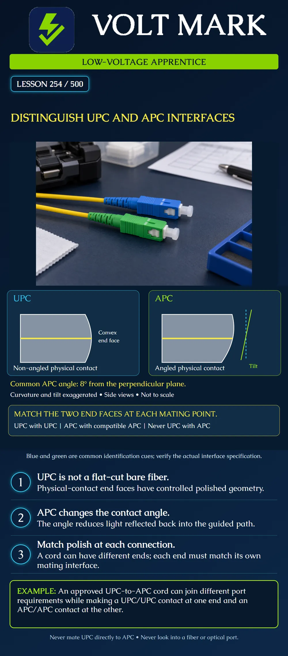
Distinguish end-face polish from connector family and determine whether each individual mating point has compatible interfaces.
UPC means ultra physical contact; APC means angled physical contact. A UPC end face is slightly convex, rather than a flat-cut bare fiber. APC adds an angle to the physical-contact geometry; a common nominal angle is 8 degrees relative to a plane perpendicular to the fiber axis. The angle reduces reflected light returning along the guided path.
The poster uses exaggerated side views to make curvature and tilt visible. The yellow line represents the fiber-axis region, not a dimensioned core. The dashed cyan reference is perpendicular to that axis; the lime reference is tilted. The drawing is not an interferometer measurement, polishing instruction or acceptance gauge.
Fluke Networks describes the end-face distinction and warns against direct UPC/APC mating because performance can be poor and end faces can be damaged. Blue UPC and green APC are common single-mode identification cues, but verify actual product records rather than treating color as complete proof.
“SC” identifies a connector family. “SC/UPC” and “SC/APC” add interface information. The same principle applies when documenting other connector families. Naming only LC or SC does not finish the compatibility check.
SENKO's SC technical brochure lists separate UPC and APC products and associated geometry/performance specifications. Use the exact product's requirements. This lesson does not assign a universal return-loss threshold, insertion-loss allowance or geometry tolerance to every connector carrying one of these names.
An approved assembly may have UPC at one end and APC at the other. That does not require directly mating the unlike end faces. Each end must meet its corresponding compatible interface.
Original paper example: Port A requirement: SC/UPC. Cord end A: SC/UPC. Cord end B: SC/APC. Port B requirement: SC/APC.
The two local contact checks are UPC with UPC and APC with compatible APC. There is no UPC/APC end-face contact in this example. The assembly still requires verification of fiber type, polarity, length, equipment support and all other applicable specifications.
Do not describe an ordinary adapter as converting the polish of a connector. It must be suitable for the intended interfaces and alignment. A shell that fits does not demonstrate optical compatibility.
Case 1: The panel record calls for SC/APC, and the proposed cord end is SC/UPC. Decision: do not mate them. Obtain the correctly specified assembly.
Case 2: The equipment record calls for LC/UPC, and the cord is documented LC/UPC at that end. Decision: the stated family/polish fields agree. That is only one part of acceptance; cleanliness, condition and remaining specifications still need checking.
Case 3: A green dust cap covers an unidentified port, and no reliable records are available. Decision: unresolved. The cap does not establish the interface underneath. Identify the equipment and its documentation before selecting a cord.
Case 4: Both ends are documented APC, but the connector families and keying are unknown. Decision: incomplete evidence. “Both APC” alone does not prove physical or optical compatibility.
The correct answers distinguish a confirmed mismatch, a partial match and missing information. Do not turn any of them into an unsupported claim that a link will pass testing.
Check the manufacturer's required inspection tip and test-port interface. An inspection tip intended for one geometry may not correctly view another. Some optical power-meter inputs are non-contact detector arrangements with their own documented compatibility; do not generalize their behavior to physical-contact connector mating.
Use the applicable procedure and authorized equipment. Never look directly into a connector or port. This document exercise does not authorize disconnecting a working campus, industrial, access-control or life-safety link.
For each proposed connection, record:
Attach a simple endpoint drawing. Review each mating point separately, rather than approving a whole assembly from a single label. If an installed assembly conflicts with the record, preserve the discrepancy and seek review before changing it.
Evaluate the lesson's different-end cord as two local contacts. At A, the documented SC/UPC port meets the SC/UPC cord end: the family and finish fields agree. At B, the documented SC/APC port meets its compatible SC/APC cord end: those fields also agree. No contact in this map pairs UPC directly with APC.
Now change only the proposed B cord end to SC/UPC. The A row remains unchanged, but B has a finish mismatch despite matching SC housings. Hold that proposed assembly and request the correctly specified B end. The original two matching rows were only interface checks; fiber, polarity, length, condition and equipment suitability still govern complete acceptance.
Mistake: Rejecting every cord that has UPC at one end and APC at the other. Correction: Check each local mating point; the lesson's cord pairs UPC with UPC at A and compatible APC with APC at B.
Mistake: Using an adapter to make an SC/UPC end acceptable at an SC/APC port. Correction: Obtain the correctly specified end face and family; an ordinary adapter does not convert polish or justify direct UPC/APC contact.
Mistake: Selecting an APC cord from the green cap on an unidentified port. Correction: Verify the equipment's actual interface record, including family and required keying, before selecting or mating a cord.
Fluke Networks, 101 Series: What is an APC Connector and How Do I Test It? https://www.flukenetworks.com/blog/cabling-chronicles/101-series-what-apc-connector-and-how-do-i-test-it SENKO, SC Technical Brochure: https://www.senko.com/wp-content/uploads/2021/09/SC-Technical-Brochure.pdf
No universal connector acceptance threshold is asserted.
Texas journeyman, 15 questions, scored by topic against the 70% mark. No card, and no account needed to start.
Free study material for low-voltage apprentices. This is a national foundation course: requirements differ by state and by local jurisdiction, and a practice that is common in one place is not a rule everywhere. Nothing here is a licence, a certification, or authority to work unsupervised, and completing it does not count as apprenticeship hours or continuing-education credit. Check the codes adopted where you are working, the licensing authority for that work, and your employer's safety programme. VoltMark is not affiliated with, endorsed by, or sponsored by NFPA, OSHA, NICET, BICSI, FOA, or any state or local licensing authority.

Electrician licensing exam prep: practice questions, timed exam simulations, and step-by-step help finding every answer in the NEC.