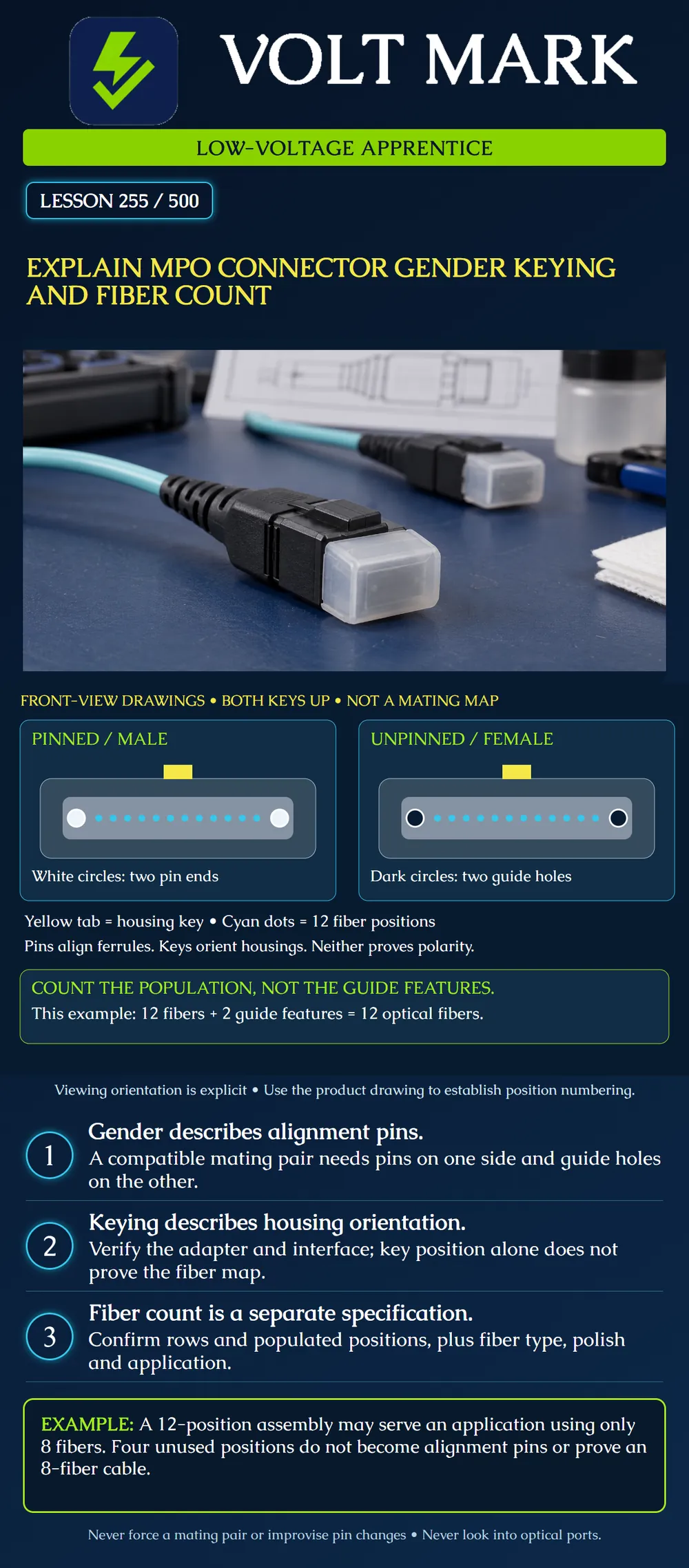
Distinguish three independent MPO attributes: alignment-pin configuration, housing keying and fiber population. Preserve the viewing orientation before interpreting a drawing.
The two sketches are separate front-view identification drawings with both housing keys at the top. They are not arranged as a mating diagram. Do not infer a key-up/key-up adapter requirement or a left-to-right fiber mapping from their placement on the page.
Each gray ferrule contains twelve small cyan fiber positions and two larger guide features. On the left, the white circles represent the ends of projecting alignment pins. On the right, the dark circles represent guide holes. The yellow tab belongs to the housing. Colors and proportions are teaching devices, not product specifications.
Gender: a pinned connector is commonly called male; an unpinned connector is commonly called female. A compatible physical mating pair uses the pins of one ferrule and the holes of the other. Do not force two pinned ferrules together or assume two unpinned ferrules provide the required alignment.
Keying: the housing key controls orientation in the appropriate adapter. Verify the exact interface and adapter configuration. Key orientation must be read with a stated view; a drawing viewed from the cable side is not the same view as a drawing facing the ferrule.
Fiber population: determine how many fibers are actually present and how they are arranged. The larger alignment features are not extra optical channels.
Fluke Networks explains these features separately and describes an application using eight fibers with the middle four positions of a twelve-fiber assembly unused. Its article includes broad equipment-port statements; this lesson instead requires checking the exact equipment documentation.
US Conec's MTP product catalog includes multiple array arrangements, including 1×12, 1×16, 2×12 and 4+4. MTP is its brand of MPO connector. The product variety reinforces the need to specify the actual interface, rather than writing only “MPO.”
Gender does not tell you where a transmitted signal arrives. A properly aligned connection can still have the wrong end-to-end fiber assignment for the application. Record pinning, keying and the position map separately.
The full path can include trunks, adapters, cassettes and patch cords. Use the approved design and appropriate verification to establish transmitter-to-receiver paths. Do not infer the complete map from the key on one visible connector.
In the poster: 12 small optical positions + 2 alignment features = 12 fibers, not 14.
An instructor's second drawing contains two complete rows of twelve optical positions: 2 × 12 = 24 fibers. The number of guide features is not multiplied into the optical count.
An instructor's third schedule describes a twelve-fiber assembly used by an application that assigns four transmit and four receive fibers: 4 + 4 = 8 active application fibers. 12 − 8 = 4 unused fibers for that application. Those four can still be physically present in the assembly. “Unused” is not the same claim as “unpopulated.”
A different assembly could be constructed with only eight populated positions. Its exact arrangement must come from the product record. Do not substitute one interpretation for the other.
A request says, “Provide a twelve-fiber MPO jumper.” The job record lacks pinning at both ends, polish, fiber category, key/interface details, polarity and length.
Do not choose those attributes from a photo. Return a completed worksheet with known fields and explicit unresolved fields. A matching fiber count is necessary information, but it is not a complete assembly specification.
If a supplied jumper disagrees with the approved schedule, preserve the discrepancy. Do not remove pins, move keys or modify a connector to make it fit. Some products support defined field changes using specific tools and procedures; that does not authorize modification of every MPO connector.
Use manufacturer drawings and prepared disconnected teaching samples.
Never look into a connector or equipment port. The conceptual front-view drawing is not an instruction to examine live fiber with the eye. Follow the approved inspection and cleaning process before authorized mating.
A fictional equipment record specifies a pinned twelve-position MPO interface and the proposed jumper record specifies an unpinned matching interface at that end. The alignment pairing agrees on paper; the two guide features are not counted as fibers. The assembly has twelve populated fibers, while the supplied application assigns four to transmit and four to receive: 4 + 4 = 8 active and 12 - 8 = 4 unused fibers.
The far-end pinning and the complete position map are absent. Mark near-end pinning checked, fiber population twelve, active application fibers eight, and overall selection HOLD. Request the far-end interface, view/keying reference and polarity evidence. Neither the correct near-end pinning nor the count establishes the far-end signal destinations.
Mistake: Counting the two large guide features as extra optical channels. Correction: Count only optical positions: the poster has twelve fibers and two alignment features, not fourteen fibers.
Mistake: Reading male as transmit and female as receive. Correction: Record pinning separately from the end-to-end position map; gender provides alignment information, not signal direction.
Mistake: Specifying key-up/key-up mating because both identification sketches show keys on top. Correction: Retain each drawing's viewing convention and obtain the actual adapter/interface requirement; two separate front views are not a mating plan.
Fluke Networks, Multi-fiber Push On (MPO) Connectors: https://www.flukenetworks.com/expertise/learn-about/multi-fiber-push-mpo-connectors US Conec, MTP Connectors product catalog: https://www.usconec.com/connectors/mtp-connectors
No universal equipment-port gender or fiber-position numbering convention is assumed.
Texas journeyman, 15 questions, scored by topic against the 70% mark. No card, and no account needed to start.
Free study material for low-voltage apprentices. This is a national foundation course: requirements differ by state and by local jurisdiction, and a practice that is common in one place is not a rule everywhere. Nothing here is a licence, a certification, or authority to work unsupervised, and completing it does not count as apprenticeship hours or continuing-education credit. Check the codes adopted where you are working, the licensing authority for that work, and your employer's safety programme. VoltMark is not affiliated with, endorsed by, or sponsored by NFPA, OSHA, NICET, BICSI, FOA, or any state or local licensing authority.

Electrician licensing exam prep: practice questions, timed exam simulations, and step-by-step help finding every answer in the NEC.